(This is the step-by-step building article. For the completed model post please go here:
http://wingsofintent.blogspot.com/2016/03/emsco-flying-wing-172nd-scale.html
The Golden Age of aviation... long
distance or endurance flight records were being often beaten again even before the
winning machines and pilots could fully enjoy their glory. Amidst this
background that is my usual inspiration field, recently three designs caught my attention; they are similar in some regards
but have distinctive characteristics. I am referring to the EMSCO (E.M. Smith
and Co.) "flying wing", and the Bryant and Vance "flying
wings". None of them is, actually, a real flying wing, but the term
(perhaps mistakenly applied by some witless journalist as it often happens)
points out to the absence of a "real" aft fuselage, being this
replaced by the twin-boom arrangement. So we have a fuselage pod, usually
short, instead of the traditional fuselage to which all other members attach.
These designs relied on refined aerodynamics and large, high-aspect ratio wings,
associated with high lift capacities and the ability to carry a large fuel
load. None of these three were particularly successful, a fact about which I
give a rat's ass. The Bryant had a push-pull twin engine arrangement. The Vance
design was quite similar to the EMSCO, but with double vertical stabilizer
instead of the single one.
There is a lot to be said about these three machines in
general and about the EMSCO in particular,
but I will say no more; if you are curious, go find about them, they are very
attractive and have juicy histories. You won't regret it, but I won't do it for
you, enough work is for me to scratchbuild these belles so you can look at them
and see how I make them. Want chit-chat, data, facts?
Look them up.
The EMSCO had two strange aerodynamic devices: the fuselage pod was a
duct inside a duct, to channel the inner airflow from the NACA cowl aft of the engine.
There was also another device that ingested air, located beneath the wing, and
pumped it through slots on the aft upper airfoil, thus creating what we call
now a blown-wing. These devices were to help the lift and speed of the plane.
They worked very well, according to contemporary accounts.
The model:
Every scratchbuilding project is a challenge, for diverse reasons. There
are always areas or parts that require some head-scratching, and that's part of
the charm of scratchbuilding.
In this case there is not even a plan, or a meager 3-view. So
I had to work on a plan, or better said, a building sketch. Once the plan was more
or less ready, work began on the model, and there a second challenge appeared: the fuselage pod, which was, as said above, a duct inside a duct. The
inner duct surrounded the pilot and copilot stations, which were located
therefore in a sort of bathtub. The air entered at the front of the NACA cowl,
passed through the fuselage main section and then the aft cone which acted like a Venturi device and then the air was expelled
at the narrow end.
The build will be illustrated, as it is customary, with images
and comments.
My thanks to Lars Opland and Alain Bourret who provided some additional useful pieces of information.
Enjoy your EMSCO flying wing
The sketches are ready. Most of the parts you see were not used, but that's the way I trick myself into scratchbuild models "Yup, I got the wheels and the prop, so basically I have 90% of the model done":
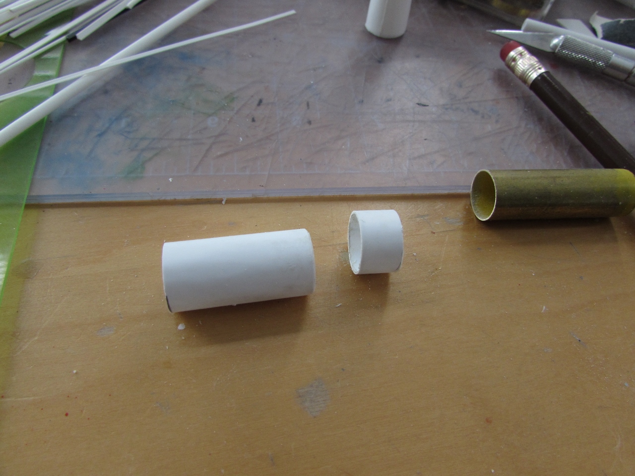
A metal tube is used as a pattern to form a tube with two layers of plastic, thus forming the main fuselage. A dowel is carved to a cone shape:
The cone shape is used to vacuform two halves:
The halves are prepared with additional parts to be joined:
The cone parts glued:
Cone and central fus.:
A segment is cut from the fus. to make the cowl:
A wood front is glued to complete the bulk shape of the cowl:
The engineering of the double-duct begins:
The front of the cone is going to be cut off at the mark to match due length and girth:

The photos show an engine shield, so I changed the metal engine and added a shield from the spares bin. The tailwheel I first separated was also replaced by another, metal one:
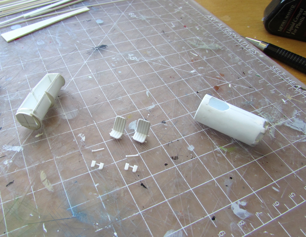
Cockpit interior parts on the making:
Tail surfaces on the making:
Booms and tail surfaces:
Many small parts have to be fabricated. In this case you can see the headrest and the curved exhaust -made from heated plastic tube-:
Metal control horns are inserted in the control surfaces. Interior parts are painted prior to assembly:
The interior is ready to slide-in the fuselage:
An Aeroclub engine and prop are prepared. These came from the stash of Armando Gil, so thanks Armando very much!:
The fuselage sections are assembled (the cowl is not yet glued):
A dry-run of the engine and cowl fit:
The headrest is glued in place:
The interior is quite visible:
The components so far. Keen eyes :-) may have noticed that the wing is missing, since I run out of styrene. But that will be quickly fixed thanks to the wonderful people from where I buy most of my hobby supplies, Burbank House of Hobbies. They have almost everything I need and they ship at such speed that you would think they have a Star Trek transporter:
The wing now in progress:
As the wing was drying, it became apparent that at some point I applied a few glue drops more than I have should, and the plastic started to soften in one spot close to the wing tip.
Not certain that I could fix that, and whilst waiting for the wing to completely dry, I made another one:
Whilst the new wing was setting, I removed the affected wingtip skins at a "rib" line, but left the spars. Then prepared a new skin and glued it back on, masking and depositing a filler line t the joint:
Both strategies worked, so I have now two wings ready to prime:
The upper center section of the wing is carved in order to receive the fuselage with the correct fit:
The wing has dihedral, something that needs to be accounted for whilst carving:
The twin booms in place:
The fuselage "pod" is attached to the wing. A thin bead of Milliput seals the joint:
Small stubs that will hold the stab can be seen at the end of the booms:
Parts that make for the booms' skids are affixed. Under the wing the raw part made from leftovers for an air intake is taking shape:
General view of the components:
The beginnings of what I hope would be the mainframe of the somewhat elaborated landing gear bogies:
Landing gear anchoring holes, ailerons engraved:
Some struts and rigging holes are drilled, upper line in ailerons engraved. The light looks a bit like the laboratory of an alchemist:
In the interim, the incredibly beautiful and superbly produced decals I commissioned from Mika Jernfors of Arctic Decals
www.arcticdecals.com
arrived in their well-protected and sealed envelope:
The landing gear is built and attached, the wing-to-fuselage Karmans are added:
The LG has some rigging that will be added later on, after painting:
White primer is airbrushed:
A view of the components:
The main components laid-out and the excellent decals by Arctic Decals:
The tail unit is mounted together and the metal airfoiled struts prepared:
A few touch-ups and painting with gloss white ensues:
Alclad gold is airbrushed on the flying surfaces:
The light green color is applied:
The light green is masked and the dark green color is applied, also on cowl and shield:
Other details are painted in preparation, here we see the airscoop for the blown wing that goes underneath the fuselage, the four wing struts and the stab struts:
The stab and some details are added and decaling commences:
Mika's decals are superb in every regard, and -as with any good decals- care is needed:
The very thin gold pinstripes are a bit of challenge to apply, and patience is needed:
CMK nav lights are separated for later use. The white nav was located on the left hand side of the aft fuselage pod, asymmetrically:
The EMSCO featured blown wings as explained earlier, so a row of "outlets" is fashioned. One of the windshields is seen held by the tweezers as metal frame decals are applied:
Wing struts are in place. Windshields are glued.
Six fuel tank caps and one oil tank cap are put in place, as well as one vent.
The positions of the nav lights are given a metal color, as per photos of the original:
The list of the things to be added is still quite long:
Control cables (6) for tail surfaces
Main wheels
Nav lights (5)
Tail struts
Cowl+engine+exhaust+engine shield+propeller
Wing rigging and landing gear rigging (about 20 segments of metal).
The nose end of the plane is ready:
Nav lights, main wheels, control cables to tail unit, tail struts, wing upper rigging in place:
A view of the belly of the beast:
Now you can proceed to the posting depicting the completed model.