(In-the-box review and building article. For the completed model post please go here:
http://wingsofintent.blogspot.com/2016/08/sbs-172nd-scale-farman-f190-completed.html
SBS from Hungary has presented another wonderful kit.
Sturdy box, appealing subject and art:
Contents protected:
Exciting contents:
Many moons (about seven years) ago, when I was trying to sharpen my skills as a scratchbuilder, I made for a fellow enthusiast a Farman F.197 (a variation of the 190 family) ambulance version (that operated in Uruguay, South América):
http://wingsofintent.blogspot.com/2014/07/172-scratch-built-uruguayan-farman.html
The effort was a decent one, and I am still pleased with the result, but the model one could produce with this kit will no doubt be superb.
Photoetched and white metal parts:
Well-cast metal parts, with detail and locking devices:
This DeLuxe (the qualifier is mine) kit leaves nothing to be desired for an enthusiastic modeler.
The price-quality ratio is very favorable, the contents impeccable, the subject appealing.
But let's focus on the details of this new marvel by SBS (the other kit I built -more than once- from them is their spectacular De Havilland DH-88 Comet racer):
-Sturdy, travel-resistant kit box
-Contents cushioned
-Parts packed in groups in re-sealable bags
-Photoetched parts
-Film instruments
-White metal parts
-Superbly cast resin
-Locating devices (hole and peg) on parts, like a normal injected kit
-Excellent decals with multiple subjects
-Color printed -on heavy stock- liveries
-Instructions with parts' map, very clear, very detailed, easy to follow.
-Highly detailed model, perfectly-cast parts, logical break-down, thin trailing edges.
-Interesting subject, with an extremely wide range of potential liveries, even more with minor changes.
-A civil subject! (there is another boxing with a Spanish Civil War plane for those so inclined)
Clear clear parts (not a redundancy, we usually have unclear clear parts):
Thin trailing edges and fine detail all-around:
So, what we modelers thought that better-known manufacturers may never be able to accomplish (either because of lack of interest or lack of technology), this relatively new, not mainstream manufacturer did, already a few times (they have other kits than the two mentioned here).So was it that difficult for outfits that have been on the market for decades to produce a kit of this level?
I acquired my kit from a local distributor, and it arrived in one day. I call that efficient! (thanks, Scott!)
There is so much more to write about this kit and subject! Let's start with this link to one of the most notable researchers of this type: Michel Barriere (Crezan):
http://www.crezan.net/
That you can explore to your heart's content, but here is the link that you can also find inside the site for the Farman F.190:
http://www.crezan.net/pag_f190/190_00_listprod.html
Components with logical and practical break-down, well protected with tabs when needed and sensibly attached to their casting blocks making removal and cleaning easier:
Nice level of detail: engine cylinders:
Engine details -again, smartly protected:
The parts are separated from their casting blocks.
CAREFULLY, SLOWLY, NEATLY, PATIENTLY. The clear parts:
The parts on this kit have interlocking devices (pegs and holes). You have to clean the parts from mold seams or the remaining ridge of the casting blocks. Some experienced modelers may do away with this pegs, and butt-join the components which may facilitate truing of the contact surfaces (not me):
Once cleaned-up, the parts' fit is good, but the usual smidgen of filler may be needed, depending on your sight and skill (the former being the issue for me):
The care on the making of this kit can be seen everywhere, and in every detail.
Why, you may ask, the fin's leading edge is not butting against the casting block making life for the manufacturer easier? because the web that is between them is much thinner, making YOUR life easier during separation and sanding. Not bad, n'est-ce pas?:
To the left, the casting blocks rubble. To the right, the parts separated and cleaned. The task did not take more than two hours, but this is not a speed competition,
TAKE YOUR TIME:
Some parts, as you may see, are
still attached to their casting blocks, in order not to loose them, to facilitate painting, and to protect them until needed:
So up to here the first impressions are excellent, this is another jewel of a kit by SBS from Hungary and I already want another one!
Building will follow and further comments and photos will be posted, no doubt.
There is a minor error in the instructions (although the livery drawings show this detail correctly). The control horn (also bellow) should not be at the trailing (aft) edge of the aileron, but ahead on the aileron, where is hinged to the wing, immediately after the separation line:
A very careful wash with soapy water and a brush, rinse and let dry. Advise: do not lose any parts, work slowly, pay attention:
I like to try to foresee any building eventualities beforehand. Here I have sharpened a brass tube (did not find the diameter I was looking for among my punch die set) to cut masks for the round windows. My plan is the glue the windows as prescribed, mask them from inside, paint the interior (so the frame of the clear parts is not conspicuous) and then remove the inner masks before closing the fuselage cabin:
The white metal parts are cleaned (not that did any real cleaning, they were almost perfect, and only the gentlest pass of a soft sanding stick was needed to erase a faint trace of the mold lines).
You can, again, tell the level of care of this manufacturer, by looking at the positioning holes for other interlocking parts, the pin appendixes on each strut, and the real "airfoil" profile, plus the sharp trailing edge. This makes me wonder, fellow modelers, what the heck have we been building all this time? why other manufacturers bestow upon us kits of less quality, many times at a higher price? True, there are other good guys out there, and I surely don't know every kit there is, but the mainstream trend is not in general encouraging :
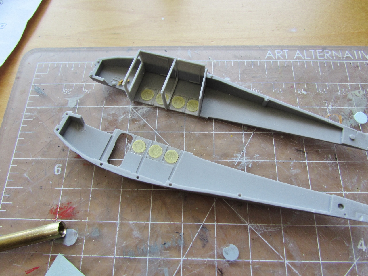
The cockpit pan as provided by the kit in one piece:
Control column (two parts) and a lever are separated (still with their web) from the casting block). The two "rods" can be replaced by lengths of wire or stretched sprue if desired:
All parts now mounted: seat, control columns, lever, rudder bar:
Meanwhile the three bulkheads and the the two-part floor were glued:
Dry-run of the cockit pan:
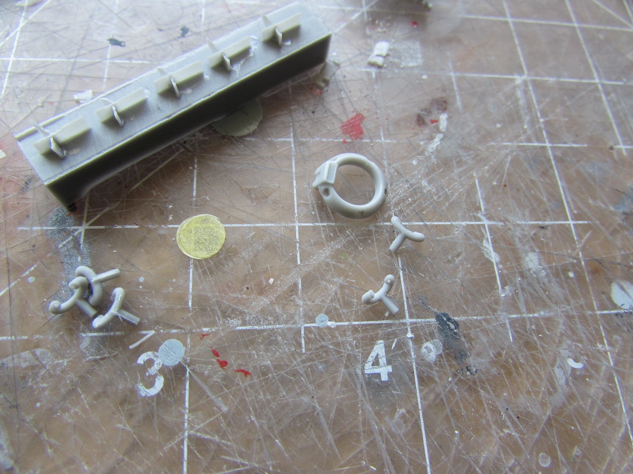
View of the photoetched sheet provided:
Other parts added to the cockpit:
Dry-fit check, all right:
There is a minor omission of a detail on the bulkheads (although you can't make a mistake, since the central one is wider at the top as represented in the drawing, and the front one is sided):
The clear parts are glued from the interior with their masks on.
Watch out, rear windows on both sides have a special shape as the aft bulkhead is inclined. The fit of all parts so far is perfect, once cleaned:
Masks are applied from the exterior too:
A general view of the components:
I decided to proceed with the engine, which is a little wonderful kit on itself.
The high quality, detail and casting reminded me of the superb Small Stuff engines (of which I made a sound stock):
First, I separated the cylinders (as a matter of fact, I used a saw, not the razor).
You may notice that the cylinders have their pushrods represented as a very thin tab. You have two options: you may remove and later on replace them with thin wire, or leave them alone, since they will be almost completely covered by the exhaust ring and pipes assembly:
The other side of the cylinders:
Sawed off (DO NOT LOSE THEM):
The cylinders are keyed (besides the instructions' visual depiction). I use a little puddle of superglue -medium consistency-, and an acupuncture needle to glue resin parts:
One by one they are glued in place, be patient, check their angles:
All aboard:
Now the ancillary parts (intake and exhaust pipes) There seems to be a double count of intake pipes, only five are needed, so you have spares or they are part of another issue of this kit :
Separation of the intake parts, in this case with web and all, to be cleaned individually:
Again, you perform some cleaning and carefully install them
As you can see, they have tiny pegs that go in holes on the engine parts:
All aboard:
The exhaust assembly is constituted by a central ring (that locks on a protruding part of the engine at the bottom) and the forked pipes:
The ring is dry-fit in place.
At this stage, I decided not to glue the pipes to the ring as suggested in the instructions (lest they did not fit properly later on the cylinder heads) but to paint components separately and glue them together close to completion. All the parts were stored on a film can and set apart to avoid damage/loss:
The instrument panel assembly is dealt with now. It consists of a flat panel, a film, a P.E. part (of which you have to bend a little part) and a resin compass.
Film is cut and panel stuck on a blob of putty:
Panel is painted white then film glued with white glue. P.E. part painted int. black and dry-brushed a bit:
P.E. part glued with window maker. As you can see, the glue squeezes out a bit, thus creating "lenses" that later will dry clear. White glue and window-maker have not very good mechanical strength, treat assembly carefully:
The compass is glued and painted. Once the interior is painted the instrument panel will be glued in place before joining the fuselage sides:
The wings have a little hole at the right position on the leading edge as a provision for navigation lights. I made them with stretched sprue, ends rounded and tinted with sharpie permanent markers. I also made a cockpit fire extinguisher I saw on a drawing from scratch. All these little details are very easy to make and add to the final model. As said, I like to deal with them beforehand, so they are ready when the right stage on the assembly is reached, and thus you don't have to stop to make them:
Here is the fire extinguisher. What? you say it looks like a wine bottle? Wait a moment....darn French pilots!!!:
Again the care of the manufacturer manifests in the details.
Venturi and exhaust pipe already hollowed:
The peg and hole system (utilized many times in mainstream injected kits) is also used in this resin kit to good effect and with precision:

I finally figured out an easy way to deal with the exhaust assembly. I dry-fitted the central ring on the engine and then glued the forked parts ONLY to the ring -this requires care and patience-:
The ring is then lifted with all forks aligned and can be painted separately:
Parts being prepared for a painting session:
Different parts are airbrushed with their corresponding colors (strategize your painting sessions, it pays off):
The engine components are assembled:
Also seen is the oil radiator (the tab-like part) that will go underneath the model's nose once the fuselage sides are glued together and the joining line cleaned up:
All the interior parts were painted a light grey:
More detail painting is done on seats and cockpit:
The cockpit pan is ready. I used made-up belts instead of the kit P.E. ones:
Inside window masks removed. Seats, instrument panel and cockpit in place:
A door was sometimes placed between the cabin and cockpit, closing the opening present in the kit's front bulkhead. Not sure if this particular plane had one, but I made one nevertheless. It will be posed open in order not to obstruct the view inside from the front and side -you can pose the cabin door open, provided by the kit as a separate part and seen in this photo to the right of the part I made:
Cabin/cockpit door in position:
Fuselage halves glued. In my copy there was a slight "decalage" between sides. If joined as per the pegs and holes the aft fuselage will slightly arch to the left (looking from behind and above), so I erased the aft-most peg to "true" the alignment (you can see a minor mismatch at the triangle of solid resin of the fuselage tail)
(I liked this kit so much that I bought another, and I am am happy to report that the second kit had perfectly matching fuselage sides, spot on):
Fuselage top glued:
The top fuselage is sanded to match the sides. Do not roundup the corners:
The fuselage bottom joint is masked and putty spread over. Some sanding is done and then the masks removed:
Then the job finished, trying to obliterate as little detail as possible and restituting what might have been lost. Eventually a mist of primer will be airbrushed to reveal areas that may need attention:
The two halves (right and left) of the stab are glued. Notice the very small marks on the elevators: there is where the photoetched control horns are glued, this is how a caring manufacturer takes care of the builder, helping! I drilled the spot all the way, and cut the horns from the fret leaving a minute pin, then inserted the horns on both sides:
When you cut the horns off the fret leave the small pin at their base, to insert in the hole in the parts. You may need to trim them a bit for a good fit (since you have two pins coming from opposite sides of the control surface):
The tailskid is comprised of two identical parts sandwiched together:
Tail horns in place:
The tailskid (which also has pins to be inserted) is dry-fitted on the holes that the fuselage has from factory. If the glue filled them, simply drill them again checking the alignment on a side view:
Right and left wing halves are cleaned and glued together. Be thorough cleaning the contact surfaces. Once more, pegs and locating holes were used by the manufacturer. Be careful not to glue the halves to a "sagging" (anhedral) effect. In fact, although the plane had no dihedral, I take the advise of Modeling Sage James Schubert (aka "Yoda") and always add a smidgen of dihedral, otherwise when looking at the model from above if the wing is flat it usually
looks saggy. Do not exaggerate this, an insinuation of dihedral is all what is needed. This is resin, and although the parts are not heavy (actually they are surprisingly light) the tendency may be to droop a bit, so pay attention at the time of adding the wing struts to preserve the effect. Remember, an imperceptible hint of dihedral only:
Putty is applied at the joint, later on of course to be sanded:
The locating holes for the aileron control horns are drilled:
The nose joint is now dealt with. There is lovely minute detail on the edges, do not obliterate it, mask the area to work comfortably:
Once more the general view so far:
Main components on a dry-run. The fit is superb:
In preparation for what might be my livery of choice, I bought from Burbank House of Hobbies, my local supplier, a few enamels to run some mixing tests on the Air France peculiar color:
The second kit I bought arrived (although this one may end up with my son for an Argentinean machine, R171), I may buy a third, since I am really itching to convert one to the inline version (Spanish EC-AAR, Cooperativa de Trevall Aeri, Manuel Colomer, there were others). The inline Farman F.194 (Hispano-Suiza 6) conversion shouldn't be really difficult...:
Canopy is a perfect fit:
The wing and tail feathers are carefully checked and then glued to the fuselage:
Dry-fit: The struts (the fore ones of metal to provide strength, the aft ones of resin) fit as usual very well, and their locating pins will provide some flexibility (sanding them down just a tad if needed) to achieve perfect fit. The struts may impact the dihedral if forced, keep checking that matter during the whole process.
Do not force them in place, since they may look curved once glued or will push the wings up augmenting dihedral. I think I'll keep all struts aside and paint them separately, then when all is done glue them (in order to facilitate even and thorough painting):
Dry-fit: The canopy needs only the minutest of swipes with a sanding stick to lock in place:
All the holes for the control cables are drilled at this point. The rudder ones are those tiny plates on the aft fuselage. On the side (not visible here) you have to mark and drill the ones for the elevator cables (look at the profiles on the kit's color printed material):
You have to mark and drill the aileron ones (they are not over the tiny plate this time, those are accesses to the pulleys):
A little forest of parts -mostly struts- on gripsticks to be painted later on:
The canopy frames are engraved. I laid a piece of masking tape and used a wood toothpick to press the tape in a bit, in order to make the contours more visible. Then I used a new Xacto to cut the masks:
The canopy is glued to the model. The entrance to the cabin is stuffed with damp tissue. White primer is airbrushed on all parts:
After the primer has set, spotted minor blemishes will be dealt with an another, lighter, more localized coat applied:
More primer is airbrushed after dealing with blemishes, at the same time that the Latecoere 28 is taken care of:
The model and ancillary parts are airbrushed:
The propeller and a pipe that runs under the engine are painted separately (taking advantage of a common painting session with another project):
The task of mounting the many struts begins:
The other parts are ready to apply by the end of the build
Work continues with the addition of landing gear elements and strut-to-wing reinforcements.
This work is greatly helped by the holes and pins present in all parts involved put there by the manufacturer. Some holes may need just a tad of enlargement to make fit easier (like in the short four struts that brace wing and main struts):
The stabilizer struts will be added after the tail rigging and elevator and rudder control cables are added:
Decaling begins (in part done before some rigging, and other part after some other section of the rigging is done). BEWARE,
the decals are very good, of superb quality, the colors are solid, but, for the same token, they are super-thin and quite sensitive. Be extremely careful applying them, using plenty of water and sliding the subjects patiently from their backing. I don't think there is any need of decal solutions:
After some tail rigging is done, the stab struts are glued in place:
I can't stress enough how delicate the decals are, here one wing letter has shriveled and died. Since I have bought a second kit, and will make it with another livery, donor decals were used:
This time the fuselage registration shriveled:
As said, spare decals were used from a second kit (since they have several liveries you can always use another one:
Slowly but surely the last stages of the build are being covered:
There seems to be a little glitch on the decals instruction: the prop is shown (for those that understand drawing) as having red bands in the front and behind (the latter would be strange). But there are only enough stripes to apply on the front (as it should be anyway). Unless only one blade had marks in the front and the other in the back, very unlikely. May be this is an error of interpretation of the laws of drawing by the person that made the art. The top blade in the drawing (that is advancing toward us) should show no stripes, since what we can see is the back part of the blade -that faces the pilot, let's say-. Or the prop had marks in the front and back of the blades (again, very unlikely) and the decals are missing the back second set.
Strangely enough, in all photos I have showing this type of pressed metallic blade, no stripes can be seen. Instead, a company logo is visible (first two images from Gallica, the third I have no idea):
The kit's instructions and prop decals:
The stripes are applied -they are still wet- as per what I believe is the correct way, although again I found no corroboration in photos of these red bands :
The last decals are applied now on top of the wing. Ready but still to be added: engine and prop, exhaust pipe, wheels, Venturi, door, nav. lights, small pipe from engine bottom to fuselage, metal rims of the windows...
A special accessory arrived today from Mika Jernfors' "Arctic Decals" shop. I have acquired before his Macchi C.94 set that comes with very nice metal-colored vinyl "rims" for the round windows. So I ordered from him "rings" for the Farman windows. Here they are (you may reach Mika using the "Arctic Decals" link located at the right of the posts and down, on the links section):
You may use your preferred technique, I used a toothpick, a (clean) rubber tip eraser and sharp tweezers:
You will use the central disks as masks for the painting of the model (my model was almost completed when these arrived):
So I applied the rims carefully. Vinyl has some elasticity, so you can work the rims a bit here and there:
The windows are given their metal rims one at the time, using the toothpick to help positioning and the rubber tip to
GENTLY press them in place (you don't wont to sink those clear parts back in):
The door needs two rings, one on each side if you pose it open (as I will):
Fit of the rims is very good, and as said there is some minor elasticity that helps:
The last detail to go in, the Venturi. Look at the beauty of this tiny part, carefully crafted by SBS. It's in the details...:
The model is now completed and can be seen in this post here at the blog:
http://wingsofintent.blogspot.com/2016/08/sbs-172nd-scale-farman-f190-completed.html