


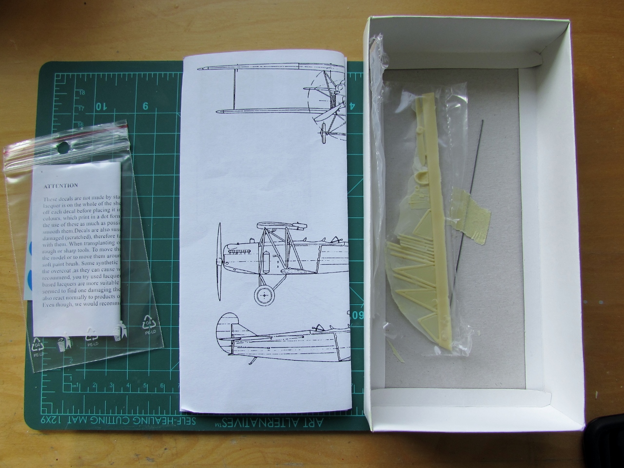
The parts are low in count and very basic, with none or minimal surface details:


As I was saying...an axle broke. In any case needed to be replaced by a metal pin:

It seems the master broke and was hastily re-glued:

A couple bubbles, present in most resin kits (but no all):

Why attach the parts to the pouring block by the trailing edege?

Zero ribbing or scalloping detail:

No stringers for the aft fuselage nor panel lines for the front.
Plain as plain:


These extra parts came in the bigger box (one spare set of wheels, two additional seats of different shape, an axle, two int. pans. and different main landing gear legs:

I confirm the mediocre quality of this kit, as stated before. No surface detail whatsoever, thick casting webs in many parts, a sort of Planet Models resin, but a notch below. The deck should have continued OVER the horizontal tail, not cut short as in the kit::


All the struttery and landing gear parts had again thick webs, are not very consistent in width, and are again too fragile and difficult to clean up. None of them can be expected to stand he loads of building and handling, as solid resin components are heavy, and are all better replaced with airfoiled metal -or steel/brass rod/wire faired with styrene- to obtain a teardrop or oval section as needed. Once more: for the price I paid, I expected more.
The inaccurately smooth surface of the wings has to be detailed. Here the fuel tanks are engraved:


There were two faired objects associated to the fuel system under the center section of the wing. They are prepared to be added later:


The kit has the nose bumps for the original engine, but this plane had a Napier Lion, thus those bumps have to go:


The nose has to be drilled in several places to represent features pertinent to this plane. By the way, for this engine the kit's prop is rotating the wrong way, so it has to be replaced:


Two props are in the process of being carved from wood. The radiators are almost there:

The props basic shape has been carved. The Milliput on the inaccurate crew positions has been sanded flush:

The new positions are marked:


Have to carve the recess for the cylinder banks of the Napier Lion:


Another pair of radiators is made for the second model. The landing gear fairing was given metal pins in place of the resin ones, which are 120% guaranteed to brake (I did both, even if only one models is going to be on wheels). Of course after I have done that, I looked at photos of the wheeled version and it's nothing like that, being comprised of three elements and bungee cord, thus, none will be utilized:


Small progress, as the election develops and we are closer to see if we can get rid of the ignorant and vulgar orange in office and restore some sanity to the world. The second engine banks are made:

The small parts that were very difficult to extract and clean up due to too thick web are recreated from scratch:


The lower wing halves are pinned and their location measured and drilled on the fuselage sides. Besides four dimples for the landing gear, no other locations are marked on the fuselage, so it's up to you to do all the measuring and drilling for wings, struts, control cables, etc.


The floaties:

The process to insert the plugs to augment the span starts:


The floats as they come form the manufacturer:

Stacked styrene is used to pack the necessary volume:

The sections are roughly sanded down beginning the process of matching the rest of the wing:

A few parts are primed. Either with the enamel paint marker or the masking approach, it seems to work ok, obtaining a subtle relief effect:

The wing is now ready for some spot-puttying and sanding, and eventually for the addition of the rib detail. At this point I can honestly say that, given the not impressive at all quality of this kit, and the work involved in the conversion, one would be much better off with scratchbuilding. Since my son is partial to the float version, I will strive to complete that one, and leave the land version for -may be- another time, as this is a phenomenal waste of time given the starting point. Some of you may know that I have tamed many a dragon, but this is just a bit silly, also considering all the care needed to work with resin:

Primer applied:

In case I ever want to proceed with the second kit, and whilst my grasp of the kit is still fresh, I am working on the other wing with a different approach, in order to keep the boring sanding exercise to a minimum. The extensions will be constructed, instead of solid, and consist of a lower skin, spars and metal pins bridging everything for solidity, and a closing upper skin:


The not very entertaining cycle of priming, correcting blemishes, re-priming, ensues. Parts for the Ansaldo are there too:

The wing modification approach for the second model works really well, much better than the block sanding. It requires careful measuring, cutting and aligning, but ends up being much faster and less brutish regarding physical exertion (i.e. sanding):


The fuselage parts are washed previous to interior detailing, painting and closing the deck. The instrument panel provided in the kit looks completely spurious and most likely was used by Omega in some modern plane kit. It is also oversized:

The strut placement is modified, and the location of two pipes (that run to the engine) are drilled on the center panel:

The ribbing and scalloping is reproduced. Only the lower wings in both kits have a sort of porous surface, that doesn't disappear with washing, priming or sanding:


Elevators are separated and control surfaces are given their home-made metal horns:

The interior parts for both models are readied. Many were scratched as the kit details are very poor:


The interior is being populated. A coupe more bits and the deck will be closed upon it:

A few images from these last days:


Et voilà!

Still have to do the trailing edge scalloping. On top is half the Ansaldo Brescia:

The second fuselage is given its interior and the deck glued on. Again due to poor fit putty is being applied. Here is where we are now with both models. A plethora of new struts and landing gear parts will have to be fabricated, as I don't trust the resin parts, which in the case of the landing gear legs are pretty poor anyway:

The fuselages get their first coat of primer:

Color is applied:

The parts are masked, and the next color is applied: green, flag blue for the rudder, aluminium for the floats top:

Fortunately no issues with the floats' paint:

The first model so far. I forgot to paint to paint the replacement strut material, and about the necessity of adding the horizontal tail and the fairing I fabricated (missing in the kit). I have to stain the prop, re-make all the struts, and paint the metal areas, plus paint the fin green:

A different approach for model two, where the horizontal tail and it's fabricated fairing are added at this stage. This second kit had much more surface blemishes, thus requiring even more work than the first. Bad resin kits are surely a pain in the tailcone. Of notice is that if you square the tail with the aft fuselage, it doesn't square with the front, a tribute to either a bad master or warping. And so it goes...

Alclad is airbrushed on the first model, to match photos, a slightly darker hue is used for the fuel tanks:


Louvers are added as per photos of the original:


I leaned my lesson (sort of), and the second model assembly is much sounder. Horizontal tail and lower wings are added before painting:


Making progress on both models. Model #2 (that will be on wheels) is about to receive the metal paint:


Details are added to the second model, three vents and the decal for the sun on the rudder:

A "metal" plaque and a retractable step are added on the other side:


Details are added to the wings, aileron horns and cables, as well as some of the piping. Each tank had its own gauge, that will be added in position, behind the protrusions on the center of the wing, angled to face the pilot :


Model number 1, on floats, gets the same tail rigging, struts, and control cable details. It still had the tail bumper, but no tailskid of course:

My previous experience with soldering is limited to electronics and a couple times arc welding. I never soldered before small metal parts for the models, always using cyano glue or epoxy. I have acquired an inexpensive 40W set and was fortunate to get it right the first try. Contrary to what I thought, the issue was not so much a proper soldering, but to position the parts accurately and securely to be able to apply the solder. I ended up using clothespins for each length, weighed-down with a metal tool. I found the use of the device with the arms with crocodile grips and magnifier I had to be utterly inconvenient and ultimately useless:

Well, the two "W" are done. It took a bit of time given my inexperience, and surely is not perfect, but now I am learning another useful skill for the hobby:

The "W" as they go into the fuselage:


Well, on its feet...er, floats, now. How would I be able to add the top wing and all the struts without knocking off that very fragile float arrangement still escapes me.

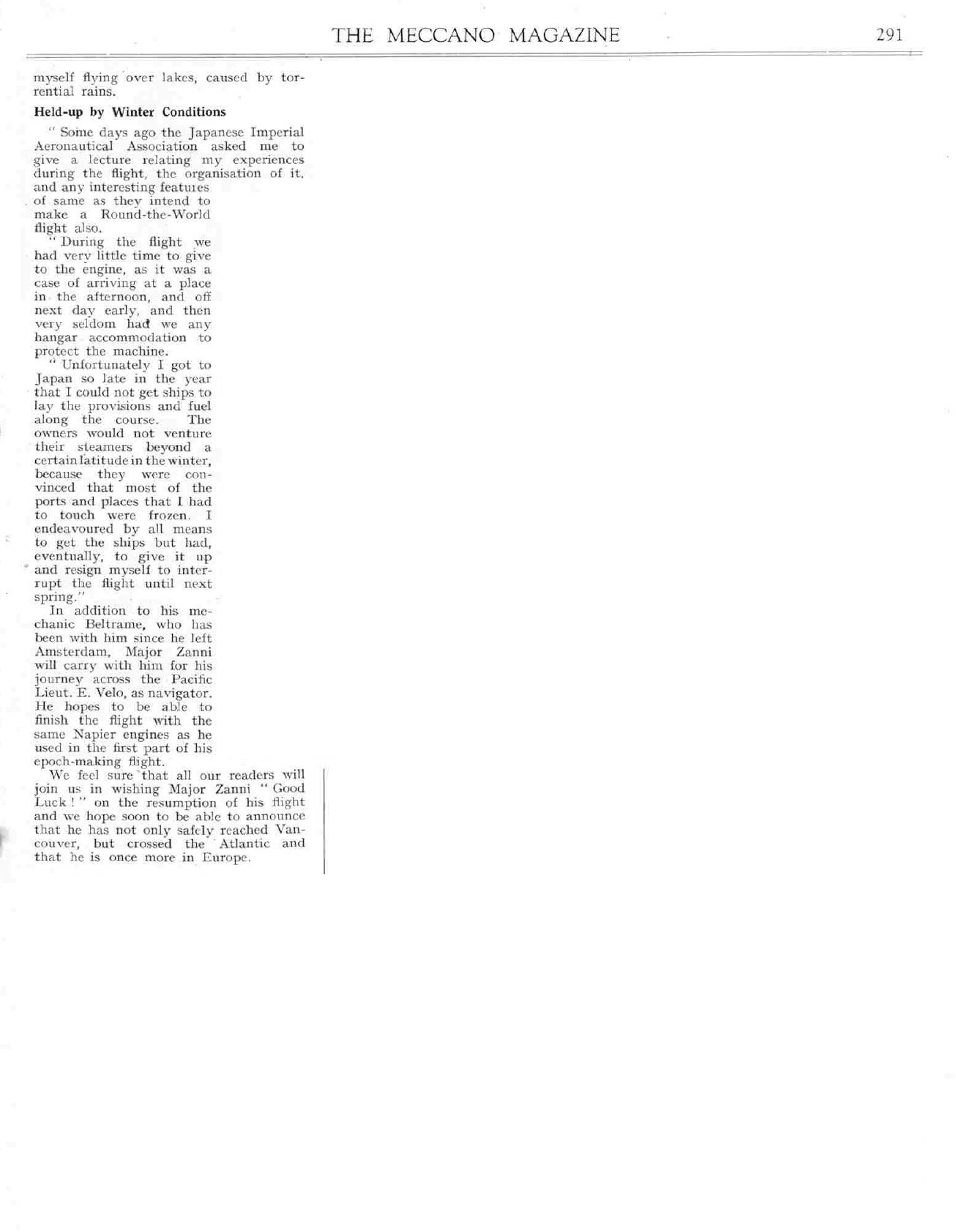
Here is an article on Zanni´s progress, of all sources, from the "Mecanno" magazine.


A tiny visitor:

And more calming sunsets:


Now both models are ready for the challenge of adding the upper wing:

Windshields and decals on:

A couple of photos of the plane ignominiously sticking its tail out of the water show prominent fabric stitching; this is replicated with home-made decals:


The N strut parts are cut to size:


The N struts are primed and painted. After some fiddling and several attempts, the upper wing is glued in place and aligned. Still to go: two fuel lines from the protuberances under the wing to the upper cowling, and eight more struts in the center area. The only necessary rigging is one short wire per side on the cabane area, no wires on the wings:

Fuel lines and pipes added, to the right the remaining eight wing and cabane struts. Still to fabricate are some detail parts for the fuel tanks area on the upper wing, plus two sockets for the navigator's instruments, and one cylinder attached to the right fuselage of unknown use. And then I will have to do it all over again for the model on wheels. Yikes!:

The landing gear wires are added. The N and cabane struts for the land version are fabricated and painted. The cabane ones for the water version are also painted in the same session:

Once flipped over, the N struts are glued in position:

Meanwhile the seaplane version is getting the last touches: all the remaining struts, two lengths of rigging wire, the two sockets for the navigator instruments, that cylinder I mentioned before to the right of the pilot on the fuselage side, the gizmos on the wing fuel tanks, prop and radiators. Perhaps soon I could be posting the completed model of this maritime version:

And the version on wheels is also completed:

Zanni and Beltrame in Japan:

To be continued.....