Fokker F.32
(Photo from the SDASM Flickr photostream)
The Mighty Behemoths
Once in a while, to commemorate the Sanding Festival that
was celebrated at the Shaolin
Modeling Temple
every time someone would complete a model, I build a Vacuformed Gentle Giant.
Here you may see the Zeppelin Staaken:
The HP42/45:
The Blackburn Kangaroo:
And the Sikorsky S.43, among others:
Execuform subject choices are very exciting, and the Fokker
F.32 is no exception.
Execuform vacufomed kits are a good starting point for a
modeling project. They do not provide details in the form or resin, metal parts
or decals, although earlier issues did have white metal parts.
They do provide the very basic parts you will need to build
a model as a clean slate. You may then add surface detail and accessories as much
as you please or like. For me, and for many others like me, they provide the
opportunity to build a model not represented by mainstream companies, and in
doing so Execuform allows you to display a replica
of an out of the ordinary plane.
I do build from time to time vacuformed kits, and I truly
enjoy them. They give you the opportunity to learn, improvise and generally
improve your modeling skills, besides the satisfaction of a more involving
participation, beyond just gluing parts together.
Since when I want a model of an out-of-the-ordinary plane it
is more likely that I will have to scratchbuild it, I am grateful I have vacuformed
kits around that reduce the building time considerably if the subject coincides
with what I am looking for. I also in the process learn a lot about the plane,
its history and details, since I have to fabricate many interior parts and
exterior details, which I do with satisfaction and pleasure. And even in the
case when there is an injected model of the subject, I may go vac, since for me
it is far more exciting.
Information on the Fokker F.32 is fortunately abundant, but
you have to invest the time to find it. As a starting point have a look on the
AAHS Journal of Spring 2012 article, the one on the Summer 1966 issue, and the
online Flight Magazine archives. But always, always, always, cross-reference:
the said AAHS Summer article has a photo of the interior of "Anthony
Fokker cabin Air Yacht", that is actually the interior of an HP42, a very
serious research blunder. There are photos and even drawings of that specific
plane, NC342N.
Beware that there were, as it is usually the case,
differences between the seven machines built. The first one had only two
vertical tails, and the elevator was balanced, plus the wheel pants were much
clunkier than on later machines of the series. Following airframes had three
vertical tails and an unbalanced elevator, and as said more kindly streamlined
wheel pants. Details in the engine gondolas also varied, having different
exhaust arrangements and in some cases a sort of Townend ring on the front
engines. Back engines also seem to show in some photos some kind of cowling,
although unusual and tighter. The Beast had four Pratt & Whitney R-1340
Wasp originally, later P&W R-1690 Hornet.
The props of the four engines (two blades in front, three
blades pushing in the back) rotated anticlockwise, if you were standing at the
front of the respective engines, which means that standing in front of the
airplane the back props will be seen rotating clockwise. The windows on top of
the cabin were tinted green (according to a Flight magazine article). Wheel
pants exhibit slightly different designs and surface patterns, besides the
difference stated above.
Interior arrangements also varied, depending upon company
and service schedule (day or night, the latter offering sleeping bunks). One
notorious Fokker F.32, the one used by Tony himself, had a very luxurious,
unconventional interior. Wing was plywood-covered. The front tip of fuselage, cockpit
sides and roof, engine nacelles and wheel pants were aluminum-covered. Most of
the fuselage and tail were fabric-covered. Doors were located on both sides of
the fuselage. Landing lights also varied. One was located in the chin of the
nose, and two on the wings, although in some planes they are on the leading
edges and in some others they are flat under the wing and deploy before
landing, as they do nowadays.
Why the F. 32 didn’t quite make it? It was born during the
depression, had problems with overheating rear engines –a common situation on similar
tandem arrangements, like the Farman F3X Jabiru and Farman F.220/2/3- and later
suffered the “no wood wings” syndrome catalyzed by the publicized crash of the
F.10 where famous coach Knute Rockne and others perished. It was also
reportedly a bit tail heavy.
But for sure it had other remarkable qualities: the number
of passengers it could carry (32) and the comfort of its installations
(ventilation, a galley, supple seats, lighting, two restrooms, wardroom,
luggage compartment, and more). It was no doubt a precursor, a pioneer in its
own right. They served basically for four years, from 1929 to 1932 and one
ended up on Wilshire
Blvd., Los Angeles,
as a gas station, but no doubt this 99’ span behemoth was a sight to behold.
The F.32 was surely noisy and exposed to the whims of the
weather, and yet I would travel on it any time, instead on the intolerably
uncomfortable sardine cans of nowadays.
In one way or another, the F.32 left its mark on aviation
history, being one of the earlier giants of its time.
Here are some
newsreel clips that would give a good idea of the portly design:
A PDF in Spanish
Of the seven machines built, and in order to study my
potential choices for a specific scheme, I started to group references for the
prototype, NC124M, and the machine furnished in luxury for Fokker, NC342N.
A very interesting detail found during research is that one
of the prototype's characteristics was a twin vertical tail, whilst the series
machines had three.
Photos of the prototype show it bare, then with a Universal
Air Lines scheme, then with an earlier Western Air Express one, and as it
happens, I found an image of the prototype with three vertical tails in a
completely different scheme, of which unfortunately not all the lettering can
be read, but it states "Inauguration of the N.Y.N.H.& H Through
Havan...", "The Everglades" and some obscured additional text.
The acronym seems to belong to New York & New Haven
& Hartford Railroad Co., perhaps one of those plane-railroad joint
ventures.
Link to image:
Not sure I would call the F.32 a beauty, as this publicity suggest, but I could call it "interesting":
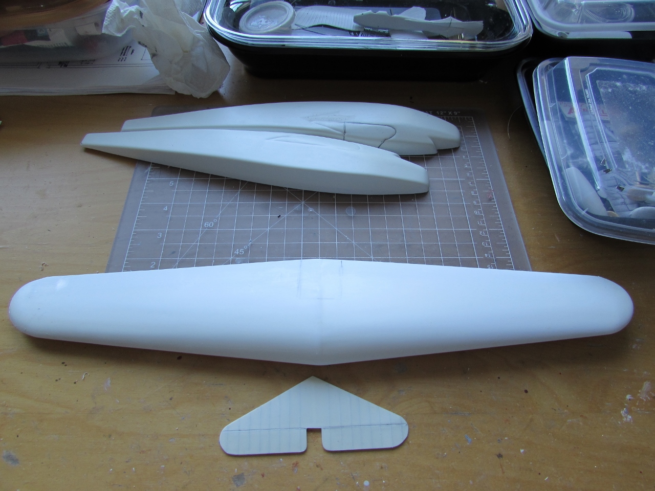
Here is what you get:
I would perhaps scratch the vertical stabilizers, as it may take less time than sanding and shaping them:
The plastic is thick, something you need for this specific model:
Again, you get the very basic shapes:
Now the sanding of the parts to get a clean, true edge ready to glue should start.
The rumors that certain vac kits were actually a secret project of the US Dept. of Health to promote exercise among naturally sedentary (i.e. lazy) modelers are unfounded.
Here the product of a good couple hours of steady sanding:
The kits provides the two types of pants, but the early one (to the right) is inaccurate, as the real thing was more angular and flat, not rounded.
The engine gondolas are of a simplified shape, as they were in fact constituted of truncated cone sections with visible joints. May be they can be covered with an adequate styrene or foil skin.
The horizontal tail may be the only usable part of the tail, as the vertical stabilizers are too chunky and rounded. They would need scratchbuilt replacements.
Beware, though, that the horizontal tail provided is only good for the series type, as the original has the compensating "ears" typical of Fokker tails. If you are doing the prototype, you will need a new one. As I mentioned, the series planes had a straight elevator hinge line, while the prototype had compensated tips:
The fuselage completely lacks -as the rest of the kit parts- any surface detail, but corrugated sections and protruding stringers are a very visible feature of the original. Skinning and/or adding stringers may be a way to solve this shortcoming. The edges were of course much sharper, an undesirable consequence of using male molds to vacuform the parts:
The wing (L.E. on top) is of a considerable size in 1/72nd, as the original span was 99'. The shape of the tips is slightly inaccurate, and the ailerons protruded a bit in the series planes, but not on the prototype.
Once more, careful study of the intended airframe is a must:
Engines, props and right diameter wheels are scrounged from the spares:
Once the engine gondola halves are carefully sanded to a circular cross section, they are glued:
The wheels are sanded, and a cap provided:
They will be mostly hidden by the pants:
The engine gondolas are tidied:
The way the engines may go:
An idea of the size:
The vac has the correct cross-section, with the flat area in the middle at the bottom:
Spacious, no doubt. 32 passengers.
The three replacement vertical stabilizers just scratched:
Spar in the making:
I see this as an improvement:
I am thinking of scratching the horizontal tail too, as it's too thick and instead of having to add the ribs relief:
Let's play the game of the three mistakes. What is wrong with this plan?:
It has the three vertical tails associated with the balanced elevator, where it should be a straight hinge line in that case. The prototype with two vertical tails is the one that had the compensated elevator, and the lobe of the compensated area was rounder, as in early Fokker designs, thus did not have a straight leading edge all the way. So the drawing inaccurate in all accounts.
Moral: in scale modeling, don't trust your own shadow:
QED:
We better scratch a replacement horizontal tail:
Gluing the laminated spar:
And almost ready:
The wheel caps are domed with a rolling ball tool:
The resin wheels, that where discarded from a long forgotten project, were riddled with air bubbles/pinholes, so putty is liberally applied. The wheel pants are assembled:
The F.32 double tandem arrangement wasn't unusual. The
Farman Jabiru had the same configuration (and the same cooling problems), as
well as the Farman of the 220 series (ditto).
(Pages from Gallica digital archives)
NC124M
Prototype. Seemingly the only one to have full cockpit roof
in clear panes.
As explained, different horizontal tail and two vertical
tails, later on the third was added as in the series aircraft. Different, rather clumsy-looking wheel pants.
A simpler interior, with seats not unlike those on the Dragon Rapide and later
Ford Trimotors. Series planes had a much more elaborate decorations and the
seats had special cushioning. The only F.32 to have P&W Wasps. Series had
P&W Hornets.
NC113N
Had partially "corrugated" (more like battened)
engine gondola section earlier in life, and smooth sections later, associated
with added Townend rings and the lettering "WAE" on the wing. Some
photos distinctively show that in later times the upper section of the wing as seen from the LE had a different
color than the rest (that was aluminum) and this may have been associated in
turn with diagonal strips on the top of the wing in International orange color.
There is a plan that shows those stripes, but misses the colored portion of the
leading edge. Later arrangements also had two large prongs (perhaps the two oil
coolers?) moved up the gondola, ahead of the main LG strut (to further help
with cooling?), the nemesis of engine tandem arrangements and their ultimate
demise.
Exhaust arrangements were also modified during the
relatively short aircraft life.
The Western Electric radio mast can be seen truncated in the
later arrangements, and there is also an unknown device on the leading edge
that looks like a landing light faring.
NC130M
Also shows the radio antenna mast, and later in life only
one Townend ring on the front engine. Earlier the two external fins were
connected by a broad strut. Small eight half-circle clear panes on cockpit
roof.
NC334N
As NC113, only later in its life it got its Townend rings in
both engines. The aft ring was different than the front one in all planes. The
same changes in surface in the engine gondolas. WAE is added at some point
under the wing. The same pair of devices is associated with the rings. Small
four half-circle windows on cockpit roof.
NC335
Few photos can be found. Exhibited at an air show at the Madison Square Garden.
Four small clear window panes on cockpit roof in the shape of half circles. In
those photos it absolutely dwarfs the Ford Trimotor.
NC336:
Few photos. No radio mast, ring on front engine.
NC342N:
Fokker's own personal plane, luxury interior, very complex
color scheme (if I could only know with certainty the colors).
The spar and wing bottom are drilled to provide ventilation and help with solvent evaporation:
As the glue sets, check often for warping and misalignments:
Once in a while use a compressed air can to vent the chambers:

This is the way I would like to solve the insertion of the wing. Removing the indicated sections, I should be able to insert the nose and pivot the wing down:
The interior no doubt will be laborious and time-consuming, dealing with the complex missing surface detail on the fuselage sides and gondolas will require extra care, but the real challenge I am afraid will be the engine gondola/landing gear clusters. 17 struts and connecting sections per side are needed, and fabrication, assembly and alignment will be, how to put it in technical terms...a freaking nightmare?
Not one but two restrooms, double the fun!
The wing looks good after the glue has set. There are no warps and the the trailing edges are straight:
Now for some sanding, as the limitations of male molds produce a not very elegant trailing edge that needs refining (exaggerated sketch below):
Dealing now with the ailerons, that need extending and re-shaping:
Looking closer to what it should be now:
The areas where the fuselage and wing will interlock are excised. Still adjustment are needed to render a close fit. Ailerons are capped:
The interlocking worked fine.
Some fine tuning will be necessary, but the setting is there:
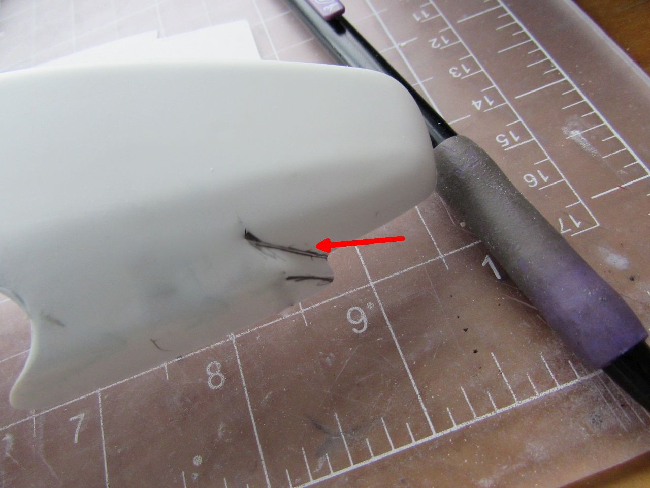
First glitch: I followed precisely the lines engraved on the fuselage sides as the wing root outline in cutting, but that was a mistake, I should have checked before cutting, as the right side airfoil chord baseline was about 2mm lower than the left. I will have to shim the right side fuselage chord baseline to pack those 2mm back:
Get familiarized with the direction of the props rotation:
I have to reverse the pitch of the three-blade props now:
Instead of painfully and not very efficiently applying surface details to the otherwise very bare parts, I decided to go the route of new fuselage sides glued on. This will allow me to pressure-engrave the very visible stringers and to square those corners in cross-section. I may be using the metal corrugated sheet you see (had it for years, no memory of how I got it) for the corrugated sections, or just use "corrugated" styrene sheets as I have done in the past:
Work on the cockpit area slowly begins:
And meanwhile, some reflections on the material I am studying:
Seating:
While drawings and some photos show the passenger version as
coach or limo configuration -pairs of chairs facing each other- other photos seem
to show the normal configuration of all seats facing forward, and many seem to
show a combination of both.
They may have been rearranged, or different planes had
different arrangements.
The passenger seats vary in shape in photos, some with
slightly pointy backs, some more oblong.
After much looking, I found and era ad by the fabrics/upholstery provider -Schumacher- that described the colors for Fokker's Air Yacht!
Office compartment:
Gray damask walls, red silk borders, silver ceiling.
Sleeping compartment:
Grey and Copenhagen
blue panels. Blue silk velvet borders the panels and curtains the berth. Couch
covers in blue and grey striped freeze. Ceiling blue shot with gold. Portieres
(curtains hanging over the doors) tan satin.
Smoking room:
Two armchairs in red and tan, two in tan.
That ladder communicated the cockpit with the cabin floor. It's just a reminder as I ordered another from a model train store with the right number of steps, lest I be chastised, ridiculed, stigmatized and excommunicated by the Modeling Inquisition, or the Modeling Brown Shirts, for defiling the Sacred Purity of the Hobby and promoting Degenerate Modeling:
A bit of work on the inst. pan., adding the engine levers console:
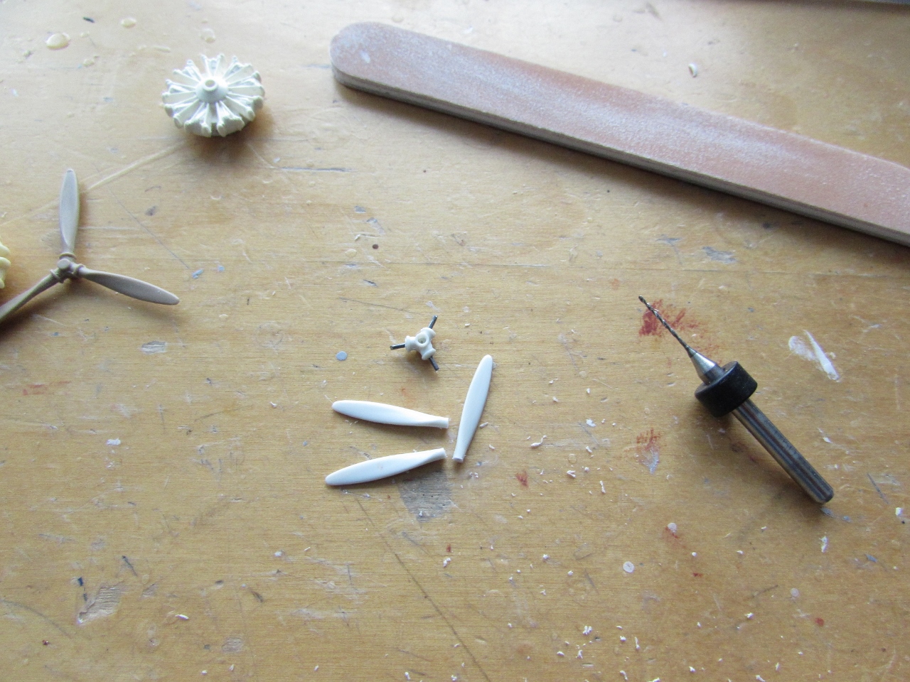
And before I forget, correction of the aft prop blades pitch. Blades separated from the hub:
Locations drilled and metal-pinned:
Prop on the right already corrected:
Both props corrected. Have to work once set on refining the blades a
bit, as of course the variation of pitch throughout the blade has to be
re-contoured too.
So I am understood: the blade should have wash-out, i.e. less pitch
towards to tip, but due to the reposition now it has wash-in, i.e. more
pitch on the tip than the section closer to the hub, thus some sanding
is due.
It won't truly correct the shape, but it will help, thanks to the
thickness of the actual part, to make the reposition virtually
imperceptible:
Believe or not, primer was applied to a few small parts.
Part of the building strategy is to get out of the way ancillaries that can be completed early on, so they don't delay final assembly later.
Fine-tuning the wing-to-fuselage interlock took more time than I would have liked. Little by little, I ended up having to pack 2.5 mm* on the right hand-side of the fuselage where the wing seats to get a leveled wing, and modify the kit's engraved airfoil leading edge that I had previously carved out, which was off by a significant way. So subtracting and adding plastic, and checking all the time, the joint is ok now, although some Milliput will be necessary when the real assembly is done.
Sometimes pictures reveal especially important information for the modeler. In this case we can see that the blue areas on the side go over the belly and converge on a point mid-line, while on the nose belly they are arched as on the sides:
Little by little, more sub-assemblies are readied:
Given the nature of the vac molding, on a male master, we have to take advantage for the cutting of the cleaner angles:
More refining will be needed to get those clear panes seating right, and the forward-raking windshield at the proper angle, subtracting and adding small bits of styrene as needed:
Finally, after many aspirins, I think I got the layout of the deluxe interior, conciliating sources and checking photos.
Starting from the nose with the luggage compartment, then a lounge with
four couches that served also as dinning room via the addition of
snap-on individual tables, then the office, then the narrow pantries,
followed by the sleeping cabin, another cabin with more conventional
eight seats, then the access space with doors on both sides of the
fuselage, and finally the two restrooms with toilet, sink, cabinets.
During this research stage, when more meticulous reading is done, I
learned some useful things that help with actual measures on the model.
The round windows on the nose were 22ctms in diameter.
The landing gear base width was 6,10 meters.
The access doors were about 1,45 x 0,76 meters.
The nose was the luggage compartment, it was lined with corrugated
aluminium below the windows, with a small radio station on passenger
planes, but the radio station was in the office of the deluxe plane.
There were two narrow pantries amidship, stated as one for cold and another for warm items.
The windows were 66 x 41 ctms.
Then hallway was about 60 ctms. wide.
The angle of the windshield was 110 degrees.
The clear panels on the cockpit roof were tinted green. It seems that
only the prototype had extensive glazing, all the other planes had a
small number (varying) of semi-circular windows, as confirmed in photos,
so some plans in that regard are inaccurate.
The ladder that communicated cabin and cockpit had four rungs, while
another used to access the nose from the ground via a trapdoor had 10
rungs.
All the color information has been already given at some point in the thread.
I can now start to scratch the cabin the interior.
A bit of paint applied. The props had the tri-color tip bands both sides, so more work is needed...
Since we are into details, here are more.
The windshield/cockpit side windows had a particular geometry, not quite captured in the molds, so here are some photos and a rough sketch:
There was a kind of windshield mustache or eyebrow, that went beyond the sides as clearly seen here below.
Some wheel pants had a straight base, while others had the more common
angled one, that helps clear the back of the pant from the terrain when
in land. The photo shows an angled one.
This below is the prototype, thus it has extensive glazing on the cockpit roof, greatly reduced in production models. The glazing arrangement is very similar, but not identical to the series planes:
Work has commenced:
Office is next:
Typewriters:
The seats for the aft cabin:
A similar windshield arrangement to the one presented before can be seen in some models of the Ford Trimotor:
A more populated cabin now:
A man can never have enough toilets...
A bit of work on the pantries:
The props are now ready, after several masking and airbrushing sessions:
The bulkheads are fabricated, still in their rough state. For this parts I use vac leftover backing sheets:
The wing is marked for a light panel engraving:
An easy-peasy typewriter you 3-year old can do:
The wing panel lines have been engraved, and some miscellanea is ready for a first airbrushing session:

Furniture is painted in different colors and hues, following what I can surmise from sources. Some of these had a decorative pattern, and my idea is to use the spatter nozzles from the Aztek airbrush, which I have never, ever tried before -or found a use for- to do that, combined with hand-applied details. Nothing to go crazy about, just to add sprinkles of color here and there. We will see:
That we are mercilessly lied to by companies and their advertising agencies or departments is nothing new.
A grim grin, a bitter rictus, invariably graces my face as I watch the safety briefing clip on the plane's screen. The wonderful, luxurious, ample habitat described in the safety clip has nothing to do with the reality I am immersed in. Even when our hard earned points bestow a first class seat under us. Not even then.
Look at this Western Airlines ad, that boasts over their "First Class" Fokker F.32, and spins some lies around it.
Well, this is of course Anthony Fokker personal plane, the one I am modeling, what we would call today a luxurious executive conversion, a one-off, that had nothing to do with the series planes that the airline had, which had the normal seating seen in many cabin photos.
Oh, the tedious chore of every day making the beds of your executive plane for this super-rich lazy 1/72 types!:
The work with the Aztek spatter nozzle did not come out exactly as I hoped.
The "grain" is vary variable, and there is much dependence on dilution and pressure:
Still, a somewhat credible representation of pattern on fabric was attained. I think and old brush or toothpick can do an equal or better job. This nozzle may do well representing mud splatter and such, but not fine work:
I am now marking and drilling the holes for landing lights and control cables. I botched the location of one of the holes, had to plug it with styrene and then cut if off :
I tried my new blade from the Airwaves set which proved to be extraordinarily flimsy:
Eventually the job was done, straightening the blade again and again:
Metal control horns are inserted into the ailerons:
Size compared to Ford trimotor
This is the color combination used on Tony's personal Fokker.
The vermilion was actually used just as a narrow pinstripe to separate colors and as tail outline. The gray represents the silver.
As an artist, I must confess that I have seen much more appealing schemes, but it reflects the taste of the times:
First coat of primer:
Work resumes on the behemoth, tidying up some blemishes on the surfaces:
Bulkheads are installed:
A loose dry-run of some of the elements of the interior:
Dry-run of the internal structure:
The fuselage closes perfectly around the interior, and the wing goes on without a problem (dry-run):
The last (hopefully) surface corrections are made. Compare with the size of the B.A. Eagle, in the same scale:
The supports for the bunk beds are added, as well as the bathrooms partition. Anchoring for the cockpit floor (dry run) is provided, there is a cut out that will allow the access ladder to be positioned later in the build. The area below the cockpit floor was used to store the luggage, and some photos show a cramped radio position but it's not clear on which of the Fokker this was installed:

The interior structure is primed. The two doors are cut out. The general window area is marked, as well as the nose portholes. The approach will be to cut out a larger area than the windows (as marked in the model), insert a full-length clear plastic strip, and then mask the windows and frames, a technique I successfully employed on a Ju86 airliner. I am not yet decided regarding two other paths I could take here: the fuselage sides had visible stringers that altered smoothness the fabric. The kit is unfortunately missing them. I already cut two "side" silhouettes in thin styrene sheet that I can engrave with that detail and then glue to the sides. But I am also thinking of having one of the sides with a much larger clear area (like those travel agency models) to show the complex interior detail, that would be almost entirely obscured otherwise. Since it took me more than a year to get here, I will give it some thought:
These is how it would work:
Advancing at a glacial pace:
To be continued...


.jpg)