

(The completed model is here:
Today it arrived.
All in all, this seems indeed a much better kit than the S.65, but we are still in the early stages of the build.
These are the things that I like very much:
-Subject, very appealing.
-Price, fair.
-Well detailed kit, convincing surface details, a number of detail
parts that enhance the build.
-Reasonable casting pouring blocks, making the parts not
really difficult to remove and clean (one exception to be discussed later).
-Reasonable engineering.
-An exquisitely detailed engine.
-The cockpit area has fine side wall detail (besides the
natural components, included too)
-Parts in general well cast (with exceptions, again to be
discussed later).
-A commendable non self-flattening box, if not a paradigm of
rigidity either.
-Thin trailing edges and flying surfaces, well represented,
with nice detail, and in general highly commendable.
-So far (we'll see as we go) an appearance of fidelity (not
like the Savoia S.65, the misses of which could be spotted from miles away).
-The wings have the panel separations, but are in one piece,
making it very easy to produce the dihedral with little effort by just pushing
carefully the outer panels up. That is a clever solution that deserves praise.
-The location of struts, control cables, etc. is well marked
and already prepared for insertion.


Things that I didn't like:
-All parts crammed in a plastic bag.
Heard of "shake
and bake" kits? Well, this is a "shake
and break" one.
-The plan that accompanies the kit is not to scale (useless
for taking measures, as with their Savoia S.65).
-There is no parts map, so you are left to guess what the
heck the tiny bits are and where do they go.
-Some of the diagrams are too fuzzy and small (engine).
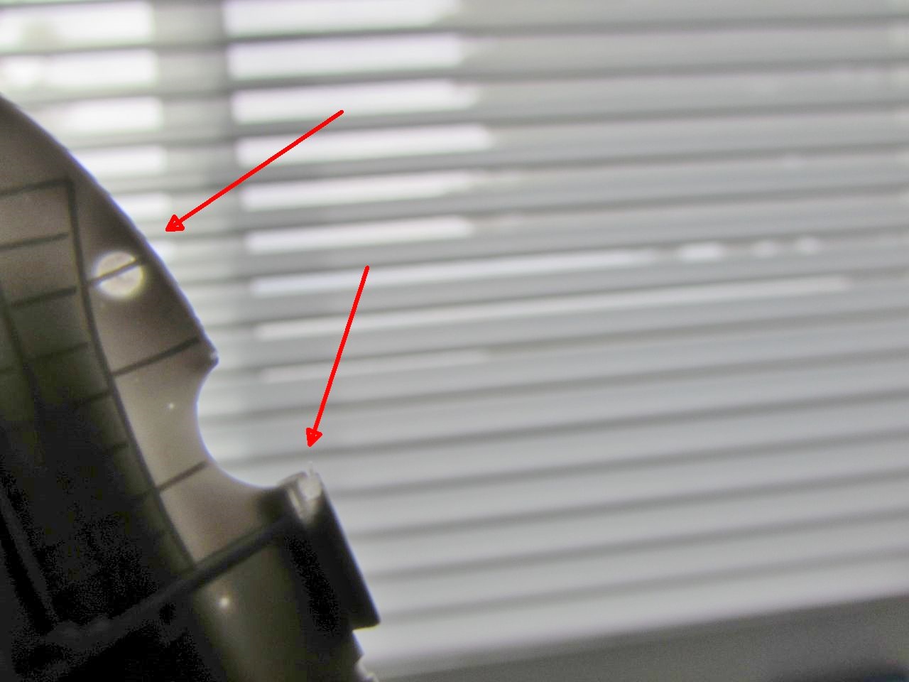
-A number of air bubbles, some opened to the surface and
marring parts.
-A few parts are too fragile to resist any load, like the
wheel forks, of which one already came malformed and broken. Interestingly
enough, photos of at least one other kit in the Net show exactly the same
problem, so it's a mold issue that was left unattended, creating a delicate
situation for the modeler that now has to scratch a very fiddly part.
-You get solid wheels (not accurate) or alternatively just
the tires, but no spokes for them, you are told to make them.
-The four-blade prop came with one tip broken. Then front
side of the blades -this is a pusher- is a little marred by the casting webs,
the other is fine.


None of these nitpickings present, so far, a real challenge
or impediment. But they are a bit annoying nonetheless.
Regarding this plane, in spite of it having been a Schneider
winner, there is no abundant reference material. I have found much more for
much less known types. This was a surprise. Still, I got a folder on it with
what I think should be enough: photos, pages from books, etc.
Construction begins:
A good, careful wash with lukewarm water and mild detergent. I use for this a coffee strainer, in order no to lose small parts:


There is plenty of good detail and lovely master-making work in the parts of this kit:


Because the pouring block is attached to the keel line of both fuselage halves, that area suffers a little bit while eliminating it, thus it will need just a touch or two to obtain a good clean finish on that area:

In ant case, these wheel forks look to me like wishful thinking, and even with the pair of rods that are supposed to reinforce it, these could hardly support the weight of a resin model, let alone an accidental clumsy handling (like putting the model on the ground in any other way that with utmost delicacy):


There were Gs under the stab, as demonstrated by this photo. But the kit only provides 2 for both sides of the rudder.
Karaya: ts-ts, go to the blackboard and write 20 times "Should do better research" (although to be frank, I also missed it the first round of checking against photos):

AND...we have another (slightly bigger problem)
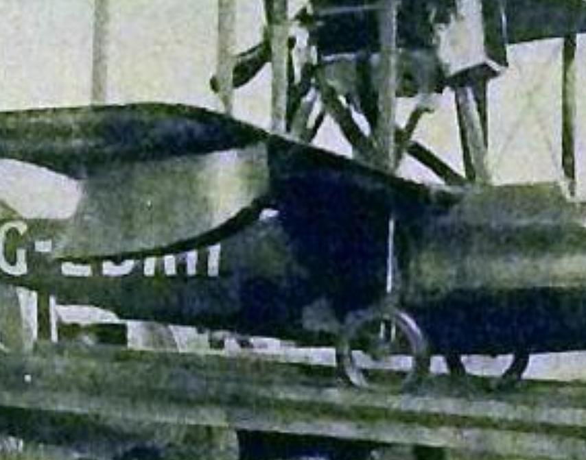
Looking at the photo above, you can see the registration letters ("G-EB") under the right bottom wing, which of course means that "AH" is under the left wing, and likely also on top of the upper wings.
Sigh....
And it seems that this has been missed in any illustration, drawing and depiction that I ave seen so far.
Ah, the delights of research...Looking at the photo above, you can see the registration letters ("G-EB") under the right bottom wing, which of course means that "AH" is under the left wing, and likely also on top of the upper wings.
Sigh....
And it seems that this has been missed in any illustration, drawing and depiction that I ave seen so far.
Going even deeper.
We know that the plane was assigned #14 for the race, but I couldn't find any photo of it with that number, until now (from Gallica, L'Aerophile Oct 1922):


So this is what Karaya missed regarding the tail struts, they are not N struts, but go like in this rough sketch. References point out to issues with tail vibration or oscillation, thence perhaps the intended remedy. There was also a wire -not drawn- triangulating the "normal", more external struts:

And yes, definitely Karaya also missed a single strut that goes from the engine to the fuselage. advancing a bit diagonally, similar to this one seen in the Sea Lion III:

The headrest area is repaired:

The position to anchor the beaching gear leg varies from plan to instructions. The former indicates under the wing struts, while the latter points out to a location much closer to the fuselage.


No locating devices are provided, so you have to resort to metal pin and very careful drilling of the stabs.
Do not forget that in this plane the convex side of the airfoil goes pointing downward, and the concave (cupped) side of the airfoil is up:
Since you are at it, drill the needed holes for the tail rigging:


Here you can see 5 number I struts and 3 number II (4 and 4 are needed). Simple, cut one of the larger to get one more of the shorter, but it would have been nice not to have to.
Not all struts are marked on the plan, so the tail group (number V) -consisting of three different struts- doesn't have any indication as to where they go, which is not very important, given that their disposition and number is inaccurate anyways.
Some (like the tail struts and perhaps the lower wing to fuselage ones) could just perhaps being carefully dropped in place, but those wing struts and engine ones will need metal pins if we want things to proceed with relative precision and safety:


So new parts can be made, which are fortunately simple:


Then the tail and wing were glued in place:


A very poor job has been done here by the manufacturer regarding clarity in the instructions and overall engineering.
What goes where has to be deduced from a small a poorly printed section of the instructions. The set-up looks vague, and possibly inaccurate, plus the manufacturer seems to have confused the missing strut that goes from the center of the gondola to the fuselage spine for some diagonal reinforcement that triangulates the array, contradicting photos and plans:

The four external struts of that array are also given pins to secure them.
Locations for them will have to be guessed and drilled on the engine pan:


The radiator is given a gloss black base:


The new and corrected beaching gear made of tube is given pins to be able to anchor it after painting of the model. The instructions call red, but photos show natural metal as far as I can tell:

A white coat is airbrushed in preparation for the blue (upper wing and main body still need the other side painted) :
After trials with several blue hues I went for what I liked best. It's called "Je ne sais quoi bleu":

Painting is completed. After some conservative (A word that has some very unpleasant echoes) drying time, the assembly will proceed. You can see that the metal-painted engine pan has been masked for this stage:

The engine castle is now glued in place:

The strut the manufacturer missed that connects engine pan and spine is added. The headrest is painted, and a missing Pitot is added from a P.E. set:

What building models in the same room where you have your office does to your computer.
My desktop computer was behaving erratically, it was high time to go inside and see what was going on. I suspected a faulty power supply, but my younger son (a computer wizard and programmer) suggested to renew the thermal paste on the heat-sink array. I removed the fan and the finned heat-sink element, and boy, was he right...

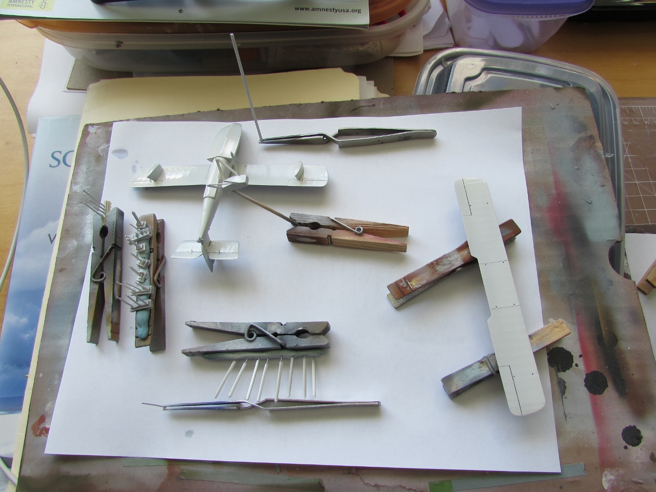
I wasn't convinced by the aspect of the kit's tail struts, and my substitutes, already painted, although a bit narrower and thinner than the ones provided, did not look convincing either. To plan B it is, and two Strutz lengths are being prepared (to the right) for priming and painting tomorrow.
Meanwhile the wing struts were glued to the upper wing, in an attempt to try a technique derived from my Lunar Module Landing gluing trick:

To celebrate that I made no significant progress, I made an Argentinian asado (vegetarians and vegans please overt your eyes):

The new strut material is painted. I just realized, after many decades, that modeling is a slow process...:

I now have to do the rigging and install the control leads, so 12 more lengths of fiber or stretchy material:


One more nerve-wracking stage is over:

Two challenges on the horizon: wing rigging and aileron linkages and control cables, and that fragile beaching gear...
Sigh...
For some builds you can easily obtain a windshield by punching a circle of clear plastic:


You can see that part of the rigging is already in place, as well as the four struts that connect the lower wing with the median line of the fuselage:

Very carefully the new beaching gear is installed.
A few touch ups and it will be ready for the decals:


Yeepee! decals arrived!:


And decaling begins.
As explained during the build the kit is missing some decals, that Arctic Decals added to their set, also perfecting the rest.
Only the bottom surfaces received the registrations, no photo shows them on top. We could assume they were there, but maybe they weren't, as it was the case with other racers.
I do have the decals to add, if need be and new material shows them:

Still cloudy, so have to wait for the photos:


To be continued....