
http://wingsofintent.blogspot.com/2013/08/172-beech-staggerwing-converted-to_28.html
A Staggering Endeavor
The Prolific and unusual family of Beech Staggerwing
aircraft evolved through several incarnations. Its elegant and unorthodox lines
have the unmistakable appeal of the Golden Age of aviation.
Less known, though, are the first pre-production machines,
which differed from the production design and ulterior developments quite a
lot.
The attempt to create the first Staggerwing built from the
Sword/AZ Model kits (they are one and the same masters-wise, but the AZ Model
is noticeably cleaner and sharper) is something I would not advice to anyone
(sort of a “kids, don’t try this at home” thing). It is a difficult endeavor
that will require a full supply of harsh language, brutal coercion, excellent
fencing Xacto capabilities and good references. The last requisite is the most
difficult to achieve. Let me explain. But before I explain, let me laugh at you
very loudly if you belong to the legion of the “The kit does not –or does-
compare well with XXXX plan / publication / source” kind of modeler. Man,
really, there is no perfect plan. Just compare two authors that did not copy
each other making the drawings of the same plane. Then compare the plan you
printed from your computer with your printer to another from another
computer/printer. Then scan a plan from a book or magazine, and print it the
same way. See what I mean? Slight differences are introduced every time the
image is processed or converted. Well, now compare the plan with contemporary
photos. See –furthermore- what I mean? That said, my suffered modeling friend,
gather all you can and sort it out the best you can (thanks Jim Irregularis of
Boingland!) It will take as much or more time and headaches than the building
of the model itself many times, but at the end...it will also mean... squat.
Sort of. But now you are hopefully closer to reality and a temporary authority
in said plane. I say temporary because two months later all the facts so hardly
learned will be data-mush in your brain. So you have a clear way: look at
everything, believe nothing, and be happy your own freaking way.
The Kit:
Good news: we have a kit of the Staggerwing released in two
boxings by two manufacturers, even with a floaty version. Not so good news: it
is not the version I want to model. Even less good news: being a fairly decent
kit with many pros, it is not the best around (short run, meaning some butt-joins,
somewhat thick parts, you know already, you have built some of those).
The two things that gave me A LOT of headaches and produced
A LOT of frustration were the two-part windshield and the struts. The struts as
molded have tiny locating protrusions which you are at risk to confuse with the
leftovers of the gates, a couple millimeters apart. If you have managed to spot
that with a “phew!”, you are not yet off the hook. The curve of the upper part of
the strut will not match that of the upper wing which it supports, nor will the
little pip align with the faint hole in the said wing. Good luck with that. I
did not have any.
I have already built one of these kits long time ago:
But I have blissfully forgotten the struggle. Hey, at least
we DO HAVE a kit of the Staggerwing in 1/72, which is fantastic.
There. Now we can proceed. Start by getting two kits (thanks Mr. C Psarras of Parabailarlabamba!). Then perhaps separate the parts you are not going to use from the first kit (engine, landing gear, tail feathers, bah, the whole kit –just kidding) and get the wings from the second kit. Now wash the parts and clean the flash, which is no doubt present in your kits courtesy of the short run technology if you are dealing with the Sword release.
The early Staggs –just to start with- had more span and less
length, so you will have to slice and splice one set of wings. The upper
–longer- wing panels in your kit number one will do now as lower wing panels
for your prototype model. The lower wing panels of both kits will have to be
hacked and re-hashed as the upper wings. Afraid of loosing detail? Don’t be,
for two reasons: the upper wing in the early machines had no ailerons (fill the
engraved aileron line and the seam where you attached the extension since you
are at it) and the prototype used a slimmer airfoil, so some little
sanding-down won’t hurt. Now your “new” lower wing (former upper wing of your
kit) will need its aileron line continued to the edge (root) fill and scribe
accordingly.
Confused? And we are just getting started. Get the right
engine from another kit or as an after market item; you need a Wright Whirlwind
instead of the P&W R985 in your kits.
To help you sorting out, here some pointers about the
prototype 17R compared to your kit (which is a D-17):
Had larger span
Had two doors
Bump underneath aileron hinge
No upper wing ailerons
Different engine
The rudder split open and acted as an airbrake
Had fixed LG (will have to glue all retractable gear parts
closed, smooth out the area, scratchbuild the wheel pants)
The fuselage was shorter and the aft shape concurrently
varied
The tail feathers were different (larger horizontal stab and
differently-contoured vertical stab)
The baggage door was on the other side (right)
It had landing lights
Tail wheel wasn’t retractable
Had slightly more dihedral –even more on lower panel-
Different nose and surface details
AND of course some other details. Elated already? So am I.
The chopping and re-joining at the aft fuselage will
obliterate some of the stringer detail present in the kit, no problema, the
prototype as seen in the museum has a metal panel at more or less that area.
The kit parts:
The kit parts:


The interior is ready to paint Notice second control wheel on "T" bar and two bars seen in photos. Kit column was discarded. I decided to pursue this course of action and close the fuselage before chopping the aft part:
 The enlarged wings receive their slap of putty. As you can see I belong to the schmutzige school of surface preparation:
 Clean and refine the parts that will close the wheel bays, making sure they will fit:
 The interior already painted, floor and instrument panel remain the be glued before closing the fuselage:
 The substitute tail feathers are scratchbuilt:
 The interior parts in place:
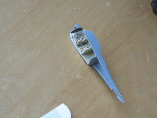 The fuselage is closed:
 The tail feathers are ready. The floor and bulkhead of the cabin were a very good fit, nevertheless the floor is beaded with white glue to avoid contamination from sanding of the fuselage landing gear area. The first part of the covers is dry-fitted:
 A section is removed from the aft fuselage:
 The cavity for the retractable tail wheel is closed:
 Other parts of the fuselage bottom are glued in place, again, pretty fair fit:
 The lugs previously cut from the wings are now put in position:
 Some putty and sanding will be needed:
 The aft fuselage is partially filled with creamy epoxy -to allow for later re-contouring- and the tail cone is put in place:
 The step is more visible from this angle. The aft fuselage is to be partially re-contoured, process helped by the kit's plastic thickness and the epoxy. Shown together with the wings they make for a pretty messy sight, at this stage. Later on, of course filling, sanding, priming will follow:
 The area that starts at the red line was a metal panel in the original, so if you can you could confine your reshaping up to that mark without marring the stringer detail if possible that would be great:
 The wing panels are sanded:
 Now we have the four panels, but be careful to fill the old locating holes for the struts. Also beware the right side up, the panels are swept upwards at the wing tips, so that indicates you how to position them:
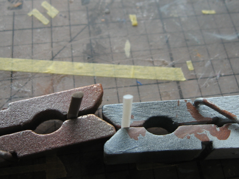
 New strut locating holes:
 The fuselage belly also at the "ugly" stage at this point:
 Some grinding of the aft section:
 Outline of the pants traced in basswood of the right thickness:
 In process:
 A bit more carving:
 a bit of hand finishing:
 almost there:
 The aft fuselage section is masked up to the line described a few pictures ago and then the rest puttied:
 The pants are vacuformed with the Mattel Psychedelic Machine:
 Another pair:
 Masters and vacuformed parts:
 New replacement engine:
 New cowl:
 The wheels and the pants:
 The fuselage belly looking better now:
 After the first sanding more little blemishes are spotted and filled in different areas of the fuselage and wings:


 The tail feathers have their rigging locations drilled:
 A new prop from Khee-Kha Art Products will be utilized (a nice, sharp resin casting):
 More sanding, more tiding up. As every modeler knows this is a kind of tedious but necessary work. The stumpy shape of the Staggerwing is evident, especially when compared to the wing panels:
 This plane had its nav lights as tear drops at the wing tips. There is a nice CMK set with different sizes and shapes and shapes of them, but you also can make your own with patience. Start with a section of airfoiled plastic (like Contrail strut material, or kit's leftovers, or sanding to the right shape a plastic strip or rod) and cut a straight end::
 Paint with shinny metal paint:
 Deposit a droplet of clear red, green, etc. Once dry carefully apply another droplet of Future:
 Each time you apply the Future (has to be done a number of times, 6,7 or more) put the rod upside down to rest and dry, that way the droplet won't just drip down the stick:
 Once the last coat is dry, a nice, clear teardrop shape is achieved:
 The four lights (one already separated and on the board) already made:
 More sanding, and repriming:
 The beginnings of the second model, NS68 with its bigger cowl are also seen here:
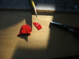
 Another method for nav lights: cut a thin stripe from a broken CD case, sand it in the shape of an airfoil -like a little, narrow wing-, then sand a "lens" and polish, then bathe in Future couple times:
 Unlike the restored museum #1 machine, the original had a fixed, faired tail wheel; accordingly a wood master was carved to vacuform a part:


 The housing should follow partially the curvature of the leading edge and partially that of the wheel pant, that was achieved working at both ends of the tube section and then cutting the "slices":


 Seen aside the parallel project, a conversion to A17FS (many differences):


 A rigid wire was used to corroborate measurements and alignment:


 Some masks are removed:


The part vacuformed:

The housing of the landing lights was made with aluminum tube:


Metal pins were used to secure wings, stab and fin:

View of the belly:


The landing light housings are glued in place:

As mentioned before, rigging in this version is quite different, due to the presence of the fixed landing gear. The flying wires go from spat to wing strut through the wing, therefore necessitating some drilling on the model lower wings. Spats and the fuselage/spat joins need some drilling too, as seen in these following images:


The landing wires will be different too (than the series model represented by the kit) splaying from the fuselage side and attaching to the fore and aft sections of the feet of the wing struts.
The base colors are applied to both models, props are painted black, then their backs masked ans painted aluminum. Some parts are kept unattached to facilitate masking and further painting:

The somewhat convoluted masking of the model begins:


Painting begins after masking:


The leftovers of the masks, giving quite an idea of the meandering but necessary process :

The props for this and the racer received their corresponding home-made decals:
 Home-made decals for the ventilation gills were printed and individually cut and applied. In this image you can also appreciate that the wing struts broke loose:


Matt black decals for the anti-skid pads were also made and applied. I am still looking for one of the wing struts which I put aside and could not yet find, after literally hours of searching, emptying boxes, cleaning the desk, looking in containers and drawers, etc. etc. Another of the multiple joys of modeling:

Found the second strut!
Searching, combing,scanning failed. Resorting to magic, praying and incantations failed.
Emptying every box and container in the vicinity failed.
Carefully scrutinizing the carpet failed.
Then it occurred to me to look at the many photos I take whilst building.
And one photo gave me a clue.
I had an amount of the discarded masking tape and close to it (apparently too close) the already detached strut.
Somehow I inadvertently put in contact the strut with the discarded tape, and it got stuck into that tape mess.
I located the discarded tape in the office trash can and went through it. Sure enough, very hidden -I went through this discarded tape ball two times without noticing it- there was the part.
Phew!!!!!:
Images of the scratched one I had started just in case:

 A general view of the parts:


 Same from underneath, tail wheels in place, cowl with exhausts:
Searching, combing,scanning failed. Resorting to magic, praying and incantations failed.
Emptying every box and container in the vicinity failed.
Carefully scrutinizing the carpet failed.
Then it occurred to me to look at the many photos I take whilst building.
And one photo gave me a clue.
I had an amount of the discarded masking tape and close to it (apparently too close) the already detached strut.
Somehow I inadvertently put in contact the strut with the discarded tape, and it got stuck into that tape mess.
I located the discarded tape in the office trash can and went through it. Sure enough, very hidden -I went through this discarded tape ball two times without noticing it- there was the part.
Phew!!!!!:
Images of the scratched one I had started just in case:


My evil plan was to mask the registration with masking tape characters on the lower wing before applying the darker red paint, but I forgot to do it in the haste of the airbrush windstorm. Since I can't produce opaque red decals on clear paper (do not have an ALPS) I printed the red decals on white stock, and will have to cut each individual character and apply it. Sigh.
Seen here the rudder decals (same trick, red on white decals that show the "cut out" regs) as well as some decals for the other model of the Stag I am building in parallel:

I trusted too much the overall very reasonable fit of the kit, and proceeded to apply Future to the cleaned-up transparencies. To my consternation, once they were dry and I attempted to glue them in place, I discovered that their fit was not good. I will have now to start to sand them to make them fit and then re-glaze them, which will be the cause of delays and general bother. The fact that the windshield comes in right and left halves does not make me particularly happier either:

The red decal on white paper is cut to suite the rudder profile

But the red decals on white paper for the wing regs had to be cut individually, eliminating all white areas:

Jim Schubert, Puget Meister of Boingland, often quotes the remark "We Modelers Are Our Worst Enemies", which applies here. I'll explain:
It was at this point in time that I recalled that I had some white lettering transfers, so each character was applied to a clear decal sheet, one at a time:

Then the decal cut and applied to the rudder, thus eliminating the need of the red printed decal on white decal paper (a solution valid in other cases, though):

Another set of transparencies from the other model in progress is sanded to fit and then Future was applied to the parts. The set I did not sanded to fit but was glazed, will be sanded and re-coated with Future for the other model at some point:

Adjusting and gluing those clear bits as said wasn't easy at all, and required great doses of patience:

The clear parts now in place, strips of colored decal make for the canopy frames:

Tail feathers in place, you can notice the "split" rudder on the first prototype and the normal one on the racer:

Metal pins again used to secure the wing panels:

Struts back in place, engine in cowl:

Using a jewelry threading gizmo to lead the rigging through the holes and fuselage:


Both tails ready, one with rigging and the other with struts:


Cowl:


Now, close to the end, another really bad fit in this kit unfortunately arose: The top of the wing struts do not coincide with the matching surface on the intrados of the top wing. This is not at all a mere matter of a couple swipes with the sanding stick, but a complete mismatch. I tried first to scrape the back area as seen in the photo. Not enough and still the front won't fit either, and dust and burrs will shower on the otherwise immaculate model. I tried to bend the upper part bit, and of course the part broke. The other strut just -once more, third time- snapped clean. So more repairs, re-paint, and more struggle with another bad area in this kit, just when everything is painted. Once more, for the umpteenth time, I ask myself why kit makers do not assemble their own kits and correct these bad areas:

After the top wings are in place and wires positioned, details begin to be applied; first the wheels, then the wires connecting rods, soon the nav lights:

Still details to go (Nav lights, Venturi, etc):
