(This is the construction article. To see the completed model you may go here:)
http://wingsofintent.blogspot.com/2015/11/scratchbuilt-172nd-scale-curtiss-robin.html
Scratchbuilding less known types often requires that a large amount of time be dedicated to research, before any building is done.
But research can be as fun as modeling itself. When you do team
research, or pool the resources of many people to create a more accurate model,
it is just bliss. And as a bonus you learn a lot and you make new friends in
the process.
I was contacted by Jack Abercrombie, curator of the Greater
St. Louis Air and Space
Museum, to build a model
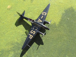
of the Curtiss Robin St. Louis 1, holder of the endurance record in 1929.
Jack has seen the model I made on February 2012 for my
friend and aviation scholar David Smith of the same plane (that was featured in
the April 2012 issue of Skyways Magazine), and wanted to produce a replica for
the Greater St. Louis Air and Space
Museum
That article (with a brief history of the plane) about the
Curtiss Robin I made for David can be seen in this blog:
Curator Jack Abercrombie has been studying this historic plane and researched
many aspects of it, and also enlisted the help of contacts, acquaintances,
relations, underworld shadow agents, mediums, diviners, etc., so pretty good
data started to emerge to make an even more accurate replica of the St. Louis
1.
Here is the account of the building process
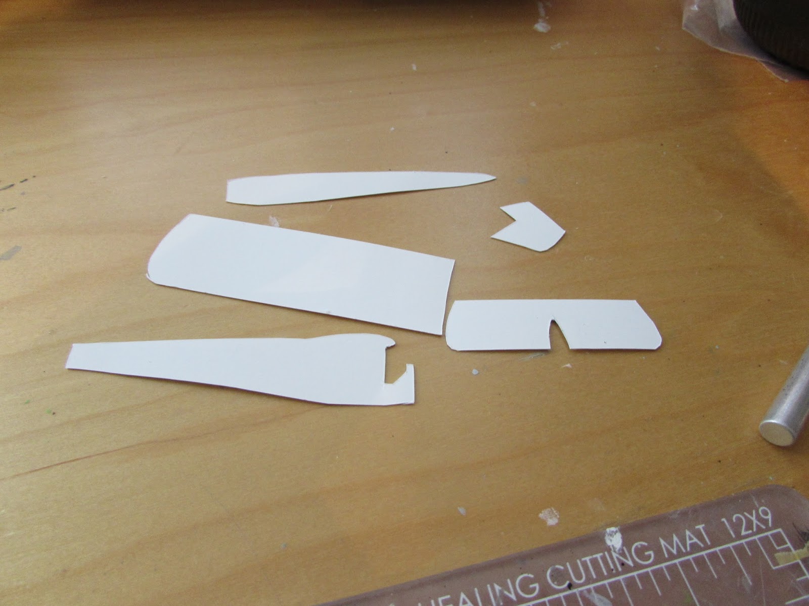
Patterns:
Flying surfaces in progress:
Internal structure:
Spar is added:
Slabs:
Internal framing of the fuselage:
The outer side with the mid-fuselage longitudinal stringer visible
A resin engine from Khee-Kha Art Products is reworked eliminating a cylinder to represent the Curtiss Challenger aero engine. The beautiful Hamilton Standard prop is also from Khee-Kha:
An idea of the size of the components:
A dome is vacuformed over a master to produce the engine shield with its ventilation openings:
Wing in progress (as a unit to ensure evenness to be later separated):
Engine ready (cylinder rows must be positioned staggered as per original) and shield trimmed:
Wing is separated:
The airfoil can be appreciated here:
A general view of the components so far:
The pilot's "wicker" chair:
Wings with ailerons and tanks engraved and airfoiled wing struts. The metal struts are from Strutz, and I owe a great deal to Andrew Nickeas of England for those:
The cylinder intakes are prepared:
And then added:
Inspection panels are opened, locations for the struts are drilled:
The tailskid made of four metal parts:

The door on the left side is engraved and the small portholes are drilled in the fuselage sides:
A fuselage tank (needed for endurance) is fashioned. On top of it was partially located the bunk for the resting crew member:
The aileron metal control horns are in place, and the control cable fairings are dry-fitted:
A mattress and pillow are made for the good rest of the pilot. Contemporary sources describe the inflatable mattress as partially exceeding the fuel tank length and resting on a fuselage structural member:
Dry-fit of the wing fuel tank caps:
The locations of the main and secondary spar are drilled and cut out
respectively on the fuselage sides. The aft bulkhead and firewall are added to the floor:
A home-made wood decal is applied to the floor; linen color paint is brushed on the fuselage sides:
The tank, inflatable mattress, pillow and certain areas of the fuselage sides are painted to:
Trusses are painted zinc chromate:
Wicker decals are made and cut to shape to cover the seat:
The seat, bed and tank are ready to put in place, have yet to make the inst. panel and control column:
Parts in place:
The fuselage is closed:
The interface section between fuselage and engine is made:
Milliput is placed on the nose filling the gab between formers, creating a smooth surface later to be sanded:
The lot as it is today:
the spars are prepared:
Fuselage cross members are prepared, seat belt is readied:
Seat belt in place, as well as another cross-member:
The top fuselage skin is partially applied:
A number of locations for other parts (landing gear, vents, struts) are drilled. The metal landing gear is made and secured in place:
All the components ready. Painting stage approaches. As you can see more locating holes have been drilled for accessory parts (like the bellcrancks for the elevator) , and other details have been meanwhile added (like the aileron control cable fairings):
The record plane has a ad-hoc structure to allow one of the pilots to get out the plane and deal with engine maintenance/issues. This structure comprehended many additional frame members and walkways, here just part of the front support:
The walking planks are fabricated:
The secondary hatch and its railings are added:
A hollowed piece of solder and a tiny support piece are added (barely visible in the forward left corner of the afte hatch) to represent the fueling trunk. The aft section of the sleeping bunk was foldable, thus hopefully avoiding fuel spills on the inflatable mattress:
Another test:
Compared to another project, an Albatros L.72:
The clear cover is glued to the fuselage front top. It will be masked before painting:
The yellow color is applied to the flying surfaces:
The clear roof is masked:
The window panes and door are measured and cut from clear stock:
The door window is masked, and the remaining clear panes are cut and orderly set aside for later use. Once the fuselage is painted, the remaining three front window panes will be cut too and added:
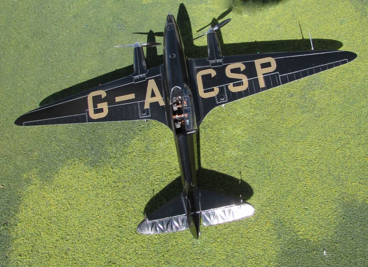
The fuselage color is applied, not forgetting the wheels and separate door:
Other small parts are painted together with the ones from another project:
The masks and stuffing are removed from the fuselage:
Part of the decals are home-made as usual:
More details are added: some vents that come out the upper cowl, wire reinforcements behind the windshield, a diagonal member on the aft open space, and so forth:
All the side windows are then glued in place:
A general view of most parts:
Once the backs of the blades are masked to preserve the anti-glare black, the prop is painted polished aluminum:
The front window panes are cut to size and glued. Then painted stock decal thin strips are cut, measured and applied as window frames:
Wings and stab are attached:
Other details are added: wing tanks' gas caps, two small vents on the top of the fuselage to the right, a patch on the covering as seen in photos, the Hamilton Standard logos on the prop, and so forth:
Engine and vertical stab added:
Necessary strut material is painted orange:
Parts of the elevator bellcrank mechanism:
The mechanism in place:
Aileron control rods in place:
A comparative perception of size:
A tail light is fashioned shaping and drilling a styrene rod:
The the "light socket" is cut off from the stem and a droplet of clear acrylic added:
Part of the images are home-made decals. The individual subjects are cut and their "fat" (clear carrier) trimmed:
The wing struts are glued in place. They have a very slight kink towards the wingtip. Also tghe wood walking planks, the clear covers of the aileron bellcrank mechanism and the tail rigging are added at this stage:
Oleo struts:
All that struttery and tubing and rods and such that makes for the landing gear, wing struts, walking planks modifications and reinforcements (about 36 parts) is mostly in place:
The more advanced the model, the more difficult to add parts, and the danger of boo-boos increases:
The navigation lights are added, plus some of the decals, the exhausts, the propeller and engine front shield, and other rods:
Only the fuselage side decals are missing, since friend and superb decal maker Mika Jernfors
http://www.aim72.co.uk/page59.html
will be working on those particular ones:
Mika's decals arrived:
I am especially grateful to Mika Jernfors, from Arctic
Decals, who provided some of the decals for this project. His decals are
top-notch quality and he is a great guy. You may contact him if you have a
special project and need to order some decals, but please give him some time so
he can better fulfill your needs.
You may reach Mika at:
mika.jernfors@ippnet.fi