(This is the building article. For the completed model post, please go here:
https://wingsofintent.blogspot.com/2020/02/fma20-el-boyero-72topia-resin-172nd.html
This kit is nothing less than a little miracle, from the works of Master Matías Hagen of Argentina.
That a kit of this incredible quality can be produced within the severe financial and market limitations that the economy and the general conditions of the country imposes, is indeed miraculous.
A fragile economy exposed to recurrent changes of policy, many times making imports/exports a challenge, is not the best environment to practice modeling in any form.
Supplies, tools and imports often reach inexplicable high prices (if and when available) and the lack of incentives combined with very limited average income make the modeler's life anything but easy.
Ten years ago I acquired and built one of Matías' first endeavors, another resin jewel posted here:
https://wingsofintent.blogspot.com/2014/07/ayacucho-maquetas-yakovlev-air-7.html
And I am now the proud owner of the first of many projects that are soon to be released.
What a pleasure when I opened the box! The exquisite quality of the masters and casting, the care put into every single part, the unbelievable level of detail, a subject that is charming and significant for the local history, all made me very happy.
The box contains groups of resin parts in several bags, assembly instructions, a parts' map, historical notes (in Spanish, more on that later), a decal sheet (more on that later), detailed decoration drawings and color calls, vacuformed transparencies (two sets, for different variants) and one of those codes you point your smart phone to access a large group of reference images of the plane on Google Drive.
The decal sheet is printed on clear stock, and you are advised that you have to provide the white backgrounds for some of the images that may need it (white decal stock may do, or painting the area white where required).
Two different sets of props and wheels are provided, to cover different variants.
Here is a translation of the historical note:
The "Boyero" (a bird found in Argentina that takes its name from
an oxen -"buey" in Spanish- driver) was born from the necessity of
the aero clubs for a civil training plane, affordable, modern and easy to
maintain. During the 30's the Dirección de Aeronáutica Civil (Civil Directorate
of Aeronautics) was the authority that regulated the civil private activity and
also provided the planes for the country's aero clubs. Although the Fleet 2 and
10 accomplished the role of basic training, towards the end of the decade a
more up-to-date plane was required. It was recommended to the FMA (Fábrica
Militar de Aviones, Military Airplane Factory) the study of a project with
those characteristics, but limited to consider products from the US to shorten
development times. Because of the predilection for the side-to-side
configuration, it was decided to utilize as the base for the design the already
known Taylorcraft B. Although the Boyero would be strongly inspired by it, it
was a local development with characteristics and solutions of its own. The
Boyero had a larger span and fuselage length, of rectilinear and simplified
shape, wingtips with washout to delay stall and loss of lift, and single
joystick that could be located in the other position. The "FMA 20"
(as it was originally called) flew for the first time in the province of Córdoba
in November 1940, and the second prototype followed on January 1941. After
successful tests it is approved for manufacturing, the rights being ceded to
the private company "Sfreddo y Paolini", but WW2 thwarted the plans.
As the US
entered the war, all strategic material like the Continental A50/A65 engines
and chromoly tubes were no longer available. In 1942 production is suspended,
the prototype goes back to Córdoba, and the second prototype is sold to the
private market by Sfreddo and Paolini in 1944. Things will have to wait until
1948, a reorganization of the FMA -that will incorporate an "Instituto
Aerotécnico" (Iae) -Aero-technical Institute- and the resumption of the
delivery of parts, and a new license for series production. The company
"Petrolini Hnos." (Petrolini Bros.) will be now in charge of
revitalizing the production of the now called "IAe.20 El Boyero" that
will be produced until 1952, when the last batch is delivered.
The total production of the Boyero was of 129 units between
1940 and 1952. Two prototypes fabricated by the FMA, and 127 by Petrolini under
license, of which 24 were assigned to the Air Force, 1 bought by a private
person, and 104 assigned to diverse aero clubs through the Dirección General de
Aeronáutica (General Directorate of Aeronautics).
In 1965 the last Boyeros under military service were sold to
the private market. Currently 24 of them survive in flying condition.
Span: 11,50 mts.
Lenght: 7,10 mts.
Height: 1,80 mts.
Weight, empty: 325 kg.
Maximum take off weight: 550 kg.
Engine: Continental A65 of 65 HP (Continental C75 of 75HP)
Maximum speed: 158/167 kph.
Cruise speed: 138/140 kph.
Ceiling: 4,000 mts.
Range: 650/630 km.
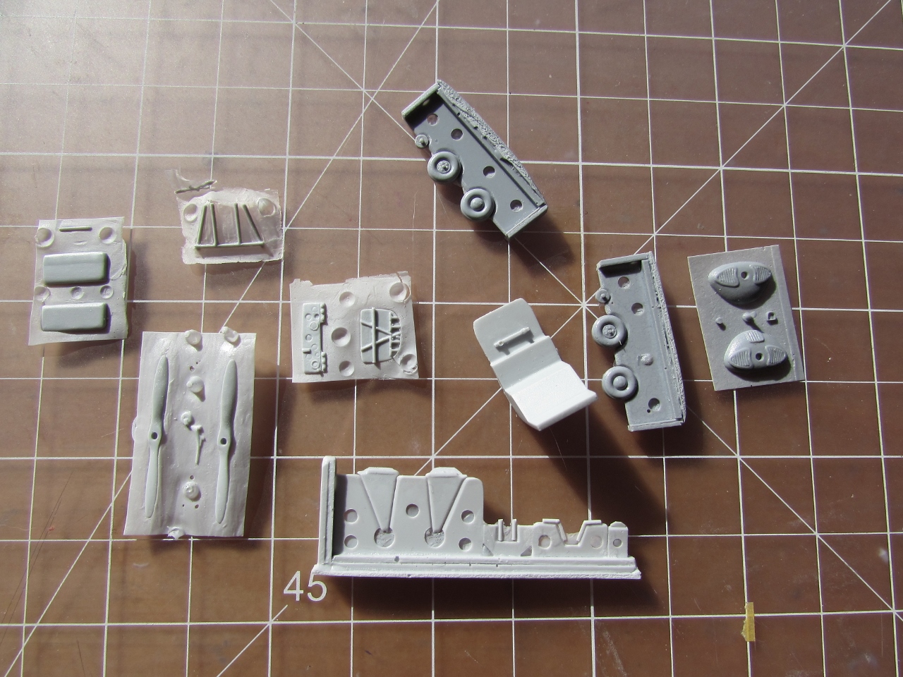
Protected contents:
Bagged parts:
Watch out for the smallest parts!
Great detail:
Great surface detail:
Wonderfully y thin trailing edges:
Look at that baby!
This is produced by one man, on his building board, without any
help and in the most difficult of environments, no access to any of the
perks we dwellers of the developed world are blessed with,
painstakingly and stubbornly, with a will of steel and incredible
talent:
A level of craftsmanship other manufacturers with easy access to anything they need may dream of.
This is the most basic level of cottage industry. In a far away South
American country. And still, a product to make anyone proud.
See what ingenuity, tenacity, commitment, impeccable craftsmanship can do, eh?
Detail on the mounting side of the LG legs:
Option of fuselage front:
Option of props and wheels:
Dedication can make wonders, uh?
Do you portray in your mind those despicable resin spawns that we have to suffer some times?
And one wonders why.
Not here, though.
No amorphous blobs, no casting webs and pour blocks you need a chisel
an a hammer to liberate the parts from, no air bubbles, no deformities,
no bad fit.
Excellence in every aspect, from a young man in his small room in Argentina.
My hat certainly goes off to him.
The casting blocks and webs never prevented an easy extraction, making life easy and clean. Take that, you shoddy manufacturers!
All parts were cleanly extricated in half an hour (take it easy and be careful, though, some parts are minute and others scale-like, i.e. fragile!
What a breeze of a job!
The parts go together like a charm (dry fit, of course):
The assembly guide, extraordinary level of detail and clarity. Again, take that, manufacturers of poor resin kits!:
Two sets of transparencies to cover different models of the plane:

The fuselage halves are given a very slight, controlled, even sanding. You may use the wing and horizontal tail to keep an eye on the amount (again, only a very slight sanding is needed) as they "embrace" the fuselage halves. When they fit snugly, you are there.
All this is dry-fit, of course:
The interior is given a coat of color:
Some of the interior parts are painted and glued in:
In an incredibly elegant act of modeling acrobatics, I managed to send the little container with the small bits to the %&&$%R$$ dimension. After more than half an hour, I was still looking for the two pegs that unite the fuselage and the side windows (that were at that point trimmed to fit). So I decided to put new pegs (white styrene in the photos) and to trace, cut and adjust new windows made from a thin sheet of acrylic. So all was quickly solved:
The other side follows:
Once the windows are in, and the seat belts were added, the fuselage halves are joined.
Check the width of the internal components. I had to sand a smidgen of all of them (inst. pan., seats, pedal frame) for the fuselage to close properly.
Once the fuselage was glued, wing and horizontal tail were added too, checking the angle, dihedral, etc., which in my case rigged itself due to the good fit.
I decided to slightly bend down the elevators and push the control stick just a teeny-weeny forward.
All the components were placed, double checked, and then with a fine wire thin superglue was run at the seams. It worked well for me.
As you can see, almost no interior can be seen... but we know it's there, as they say:
The fuselage seams will need a delicate touch with filler or putty.
There is a balance between sanding the inner face of the fuselage sides, and the fit later of all the other parts. If you sand too much, then the wing and stab, that "embrace" the fuselage, will be a little loose, and the vac windshield may end up being a tad wider than needed. I got a good fit with wing and stab. The resin part for the face of the nose is a smidgen smaller than the fuselage front now, and the windshield a hair wide, and here is why I write about balance. If I would have sanded more, the front of the nose would be spot on, but the windshield too wide.
So I sanded the nose sides, top and bottom -just a very small touch-, for a perfect fit of the nose, and also sanded the relief that is meant to align the front part, since I didn't need it and was a bit in the way.
Two pieces of masking tape are placed along the two inner stringers to limit the working area, then later putty is applied sparingly and sanded. It's a good idea to protect the interior somehow (I use damp toilet paper) so dust doesn't get in:
The prop and wheels are painted (I will use the wood color one and the uncapped wheels, but painted them all):
The belly receives the same treatment, masking using the inner the stringers, and puttying. There is some
very nice detail there, but I can restitute it once the sanding is completed, and I rather do this than work around it. If you don't feel confident, use for the seam liquid putty, typewriter corrector (white-out), or whatever is that you prefer:
I mentioned before that you have to provide the white background for the decals that need it (they are printed in clear stock with an inkjet printer). So I made a copy, cut the pattern away, and used it as guide to trace on the back of white decal stock. Then I cut the individual images:
Be sure to have a smidgen inside, so the white doesn't show:
There is a resin part for the rudder control horn, but it jumped away from the same "small parts" container that I sent flying, so I made another from aluminium:
The seams are sanded and cleaned up, the details restored:
Time to drill the locations for the tail rigging:
Watch out for that tiny castoring and springed tailwheel assembly, faithful to the original and in scale, but it won't admit knocking around:
The white background decals for the rudder flash are cut using the same method that the chevrons:
The very small exhaust stubs have their end hollowed. Talk about minuscule detail:
There is a hub part that unites the leg with the wheel, with pips on both sides.
This allows you to paint them separately:
... so I had to fabricate another.
Piece o' cake, with a slice of styrene rod of the same diameter...
... and then drilled and a small styrene rod glued-in:
Don't forget to insert (without gluing) the prop axle from behind the face part before gluing it to the fuselage front:
Front and landing gear added. The legs have precise, well thought, and sound locating devices:
On its feet:
With the remaining parts:
The fit of the windshield is good, but in my sample it needed just a little trick to perfectly fit...
...I very carefully cut where that red dotted line indicates -the shaded area marks the position of the wing leading edge root), it's a minuscule cut, but it allows the "side" of the windshield to align with the frame more precisely. Use the right windshield for the version you are building, since two are provided (that are not the same):
Remember I took a photo of the tiny tailwheel?
Well, I left it there and forgot about it.
So it was swept away by the forces of nature.
And I had to fabricate another one, from very thin aluminiun strips (soda can) glued together as a spring, and a punched out disk, plus a yoke an a stem:
The windshield is bathed in floor polish:
And what do you know, I found the tailwheel at the very bottom of the office trash can, where I may have swept it as debris...again. Sigh...(also found two landing gear scissors that I was not looking for):
The transparencies are masked, the cockpit stuffed with tissue paper, and the model is ready for a light coat of primer.
I will leave the windshield and struts apart until painting and decaling is done.
The tailwheel is painted separately:
Primer on, still a few little things to touch-up:
Size compared with the Beech 18:
A light coat of white, before the final coat of ivory:
While the paint dries, the individual subjects subjects of the decal sheet have to be separated (continuous carrier) and trimmed closely.
The white backgrounds we are warned in the instructions are needed for some of the images were prepared beforehand, and were posted somewhere above in the thread.
If you do a white undercoat as I did, you could also mask the areas you need to be white before applying the final color:
The level of detail can be seen in the little things, like these minuscule pips to help locate the struts in their marked position:
The ivory color is airbrushed:
Decaling proceeds.
In order to minimize the effect of the carrier, I cut the individual letters of the registration:
I had placed the chevrons pointing outwards, but they should be pointing inwards, so they are relocated:
The landing gear remaining components are added. The wing struts have a good fit, but require careful handling and positioning:
I had a couple of minor glitches with the decals, which I commented above are home-made. So I decided to commission a replacement sheet from Arctic Decals. You may see here that I removed the chevrons on the top, that came along while I tried to remove the top color decals I wasn't completely happy about.
The rest proceeds as normal:
Still to do:
Complete decal application, paint front grills, add steps (one per side), add exhausts (two), add tail rigging, add rudder control cables, prop, windshield, fuel cap:
While I wait for the spare decals I commissioned, I added the stirrups, the exhaust pipes, the tail rigging, the rudder control cables, and the diagonal reinforcements of the landing gear legs. I also painted the front grills and put in place the prop. I will add the windshield the last:
The rescue set from Arctic Decals arrived:
To be continued: