

(To see the completed model please go here:
Continuing with the modeling saga of less-known types, that
nonetheless made significant contributions to aviation history and development,
not to mention aesthetics, here is the Sopwith Bat Boat of 1913, credited as
the first successful amphibian built in the UK.
Thomas Sopwith came from the boating field, and used in the
Bat Boat a type of construction technique called consuta: https://en.wikipedia.org/wiki/Consuta
The Bat Boat design went through several incarnations. The
model here represents the plane as it won the Mortimer-Singer amphibian
competition of 1913, with retractable landing gear.
Photos show that the plane in this configuration had an
inline engine, the fore plane removed, twin rudders under the horizontal tail,
and canvas fairing on the space between lower plane and fuselage.
Photos show other versions with what looks like a rotary
engine, different radiators, different tails and other changes.
Beware that some plans out there mix features of them all,
and are in general suspicious, therefore always rely on photos and compare them
with the plans.
There are, as far as I know, two 1/72 kits of this plane,
the Joystick vacuum-formed I am using and a Luedemann resin kit, that to my
eyes looks just a wee-bit chunky and an itsy-bitsy heavy-handed.
I got this kit thanks
to the good offices of fellow modeler L. Santos, who saw it in shop and called
me to see if I wanted it (you already know the answer), thanks, L.!
For those unfamiliar with this brand, you get the usual vac
sheets, but also white metal parts and airfoiled struts material, both
facilitating building greatly. In this case rods to build the frames that support
the tail were also included.
The kit came to me started. The vac sheets have been primed,
the wings separated (but not cleaned or thinned), and the fuselage sides where
already cut and given some reinforcement tabs typical of what we vac builders
use. I do not particularly appreciate started kits, but what little it was done
to this kit was ok, so I set to continue the build.
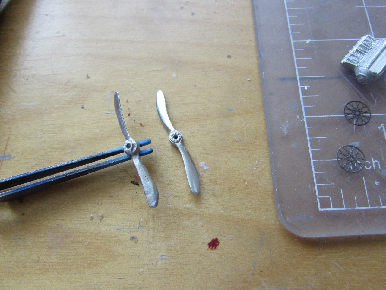
The kit allows for different versions to be built. The metal
parts consist of engine, fuel tank (so-so), prop (very poor) and wheels
(inaccurate, solid ones). The vac floats are better replaced with a plastic rod
and cones or similar, since they are not particularly good.
The kit as I got it:


And never came back:


Now, if you are a newcomer to the vac universe (well, the field is quite smaller than the universe, to be frank. One could say " vac galaxy", may be... but actually "vac world" would be more accurate. You know what, let's go for "small field") you may be asking yourself:
"-What the builder does in this cases of just one surface wings?".
There are several answers to that legitimate question:
1) Ignore it. Only modeling perverts and modeling voyeurs try to look underneath a model
2) Use another, very thin sheet where you have previously engraved the ribs -ribs underneath tend to be very faint, unlike upper-side ribs, which are more showy, so to speak. Like if they were coming from the financial district or something, the little basterds.
But his method usually results in undesirable thickness.
3) Engrave the ribs with a tool on the surface...
Ladies and gentlemen, I give you (trumpets blow, drum roll....)
The Double Engraver ™ !!!
A tool useful for the gentleman as well as for the lady, for the children and the elder (who shan't, under any circumstance, use it), for the office, home, garage, basement, bunker, boat, motor-home, camping, space travel, time travel, to defend yourself against Martians, the tax man, and a thousand more uses!
Only today, at the incredible price of... NOTHING!
You can build one yourself!
Just put two (yes, TWO) blades on your Olfa cutter, perfectly aligned, and you will be making not just one, but TWO, perfectly parallel engraved lines AT THE SAME TIME!
Need more space between them? put a ..... SPACER! yes, another revolutionary invention!


I also have a backup plan of aluminium/brass/nickel alloy tubes in case results prove disappointing:


1) Tea dispenser
2) Milk dispenser
3) Sugar dispenser
4) Sandwich type selector
5) Scones retractable rack
6) Clotted cream-on-top / Jam-on-top switch
7) Fog level indicator
8) Imperio-Meter (shows which countries/territories the Empire is loosing or gaining at the moment)
9) Mnemotechnic scrolling list of names of relatives (wife, progeny) and club members (the old memory is not what it used to be)
10) Bell to summon Jarvis to the water to park the Bat Boat


Why is that many kit manufacturers have photophobia?, that is, the paralyzing terror that impedes them to look at photographs of the type they are producing?
Well, I can look at photos. They show that the leading edge cut out is only above the cockpit opening, and that the struts in that area should be aligned with the others:

Ts-ts. Mr. Archer...
The cut out on the trailing edge seems (although I do not have a good photo of this specific configuration showing the area) to be ok:


I selected plastic over my usual choice, brass Strutz, because plastic is far easier to shape when the struts are not just straight uniform sections:


Therefore I have to discard the kit part and most likely fabricate a Green E.6.
I was able to find a Wikipedia image of it, but just of one side. Hours or research online and in within my files, and I still can't find an image of the other side.
To make things better, the Flight Magazine archives (a place where it could most likely be found) are being revamped and offline.
Sigh....
A new engine is fabricated (thanks Adrian for the engine image!) and it's ready for some paint:


The plan is to mount the upper wing, then the tail rig structure to the wings, and after that the tail feathers.
That sub-assembly will be glued to the hull, and then the engine, it's struts, the fuel tank and the radiators will be added.
Last would be the landing gear, the hull-to-engine-bearers struts, and details.
(all this sounds very good in my head, we'll see what reality, that tends to be sometimes not very agreeable, dictates)

Besides the above-mentioned rectification of the lower wing leading edge cut-out, the geometry of the landing gear struts needs tweaking so:


It was decided to first install the engine, fuel tank and radiators, to have unimpeded access, and then glue the tail booms:

In the background, to the right, the engine bearers-cum-struts can be seen:

Do not forget that this plane had a pusher configuration, thus the exhaust has to point towards the prop:


The engine, already painted black, is given a mist of metal color, in preparation for detail hand painting:


After the oil dries, a coat of varnish will be applied:


I am fabricating "pulleys" to install where needed:


Almost there... may be tomorrow I can add the last touches and take photos, if weather allows:

Here a few images as a teaser, with not very good light at this time and stormy skies:


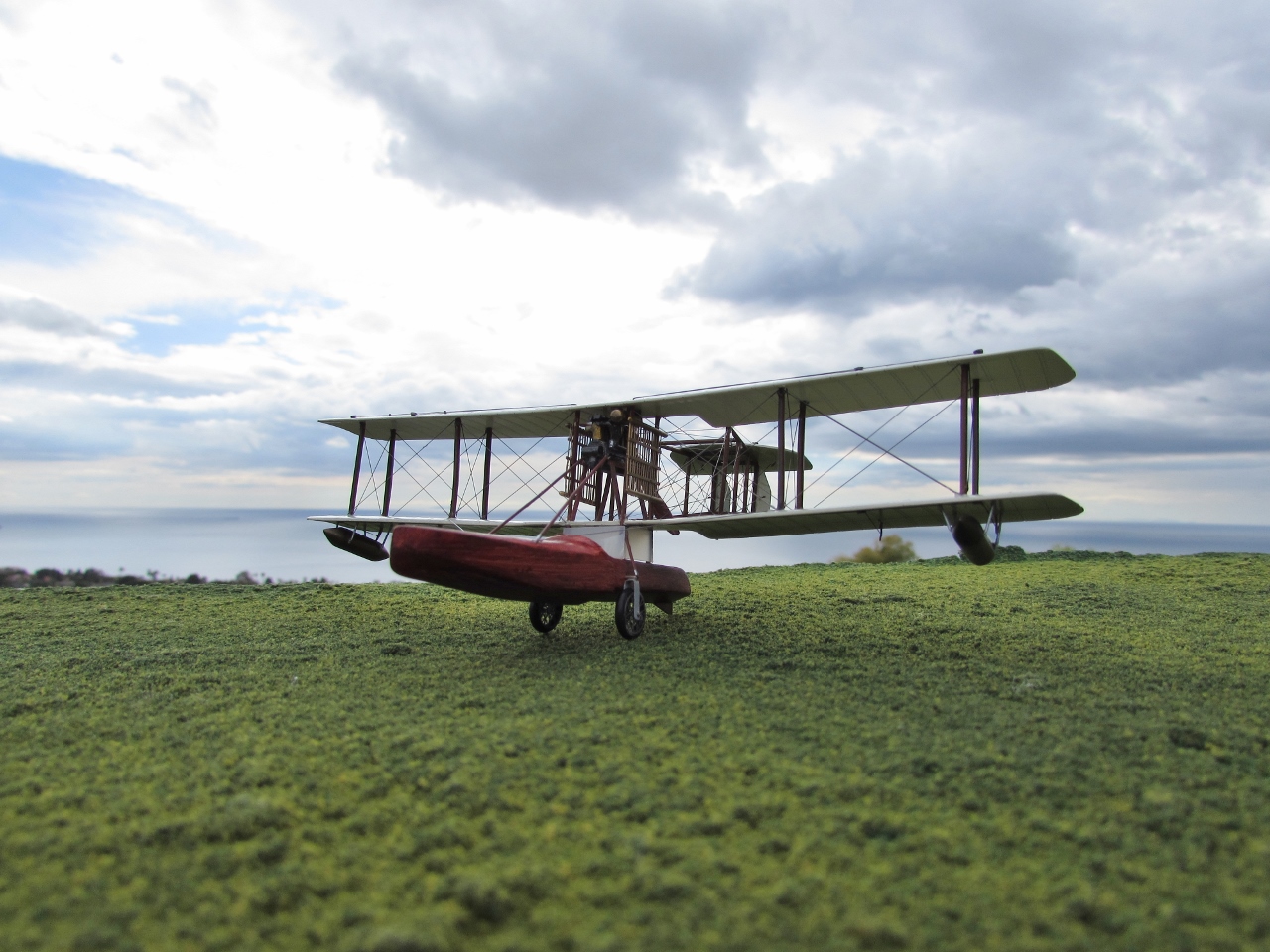

To be continued....