(The completed model is here:
As I approach the relatively slower stages of the priming, painting and finishing of SBS's newest release, the Farman F.190 (see previous posting), I decided (since you have to wait for primer and paint to dry) to build their first release, since I got a kit for a good price.
This already somewhat old first step for SBS is a very appealing subject, but the kit has some teething problems (unlike newer releases) that I wanted to fix to be able to build this iconic record breaker.
Adjusting the SBS Latecoere 28.3 "Comte de la
Vaulx" kit:
This was as said SBS's first release, it caught the attention of a
large number of modelers because of its great detail and accessories.
Now SBS has released other kits, which are a paradigm of
perfection, but this first release evidenced some first-steps problems, now
fortunately over with in the models I mentioned (and happily built): their De
Havilland DH88 Comet racer and their Farman F.190.
I mulled over building the Late 28 first release a long
time, knowing that to correct its flaws some work had to be done.
Now,
this is the work of love of the person that made the masters and the
manufacturer that kitted it, it took them a lot of work and time and resources, so criticism is always
a difficult endeavor because it may upset or sadden someone. The kit has
some great points and a few shortcomings, and we are very grateful that these guys released a kit of such an important plane.
You could build this kit as it is (I have seen several
already built) and the flaws may show to the trained eye and not the general
public, but I just can't leave it in peace. Finally, I gave up to its appeal,
redeeming qualities and the fact that it has South American connections.
To the task at hand:
Wing:
The first and foremost, and most evident flaw is the kit's
wing, which is a bit of a flattened and
thick pancake. Whereas airfoils exhibit a curved surface, this wing has a large
central area of the cord that is as flat as the Pampas where the Late 28.1s used to fly in Argentina.
The leading edge is too thick and blunt.
The trailing edge should have very subtle scalloping,
clearly visible in photos.
The ailerons show on photos as much ribbing as the wing, and
the same trailing edge subtle scallops.
I had to do some kind of drastic and extensive work (but not really
difficult) to remedy those issues, you will see it bellow.
Canopy:
As the canopy's upper and aft portion is inextricably
associated with the wing, it has to be modified too.
Details:
Some details are missing from this rendition of the
Late 28 (but present on the SBS newer releases), most conspicuously:
Control linkages to ailerons (horns and rigid linkages under
the wing, two per aileron, ailerons were a two-part affair)
Floats wire rigging
Tailplanes' rigging
Tail control cables
Navigation lights
and other smaller details.
Nose:
The nose of this kit earned some criticism. It may be a tad
stumpy, but the Comte de la Vaulx seemed to have a shorter nose than other Late
28.3s anyway, as can be seen in photos, which show some slight shape variations too.
I'll leave it as it is, since it is not a bad match to my
photos.
At some point I saw on a magazine a review of this kit (long
ago) where the author stated that some person in France had a resin replacement
nose. I tried for ages to get a hold on him (his website is the best example of
an online dysfunctional labyrinth) and I never got a reply to my many emails sent at
different times, neither did a couple other friends, so do not count much on that.
The level of detail in general in this kit is appealing, if
a little overstated on the flying surfaces and also on the floats. It has a multi-part cockpit (that lacks the
rudder bars but has other minute detail) with defined relief and a number of
gizmos, completed by an assortment of etched parts. The aft cabin (after the
solid space where the tanks were) has no detail, but the door can be posed open
(as well as the cockpit door) so most likely I'll be filling that up (the
bathroom, the modeling delight and joy of my friend Alain Bourret) is exactly
opposed to the door, so temptation is big.
One strange technical issue on this kit is the absolutely
solid and massive resin pouring block to which the fuselage bottom is attached.
This is not a big deal, it just takes a little time with the right tools to
eliminate it, but is awkward and cumbersome. You will have to do the engraving
(matching perhaps the side panel lines) of the panel lines once your fuselage bottom is ready and
clean.
Contents (all came bagged and well packed):
Parts attached to their pouring blocks. Notice also the bagged clear parts and the photoetched set with instruments' film:
Parts detached (took less than two hours) from their casting blocks:
Level of detail:
The massive block of the fuselage:
Really clear parts:
Free now:
The wings, which feature some ribbing, need to be corrected, they have an inaccurate "flattened" airfoil:
They are completely sanded with an electric sander to correct airfoil, working carefully and gradually, which of course does away with the detail, that will be reinstated in other way:
The wing halves are joined, and the top of the canopy sanded down to properly align it (mask the rest of the transparency while doing this to avoid scratches in other areas):
The center section is "augmented" just a bit (as per photos) with putty:
The work resulting in a good match and more pleasant (and true to the original) wing:


My evil plan. The ailerons are glued with a very slight deflection up and down. The masking tape will be placed at given intervals to create "ribs" by airbrushing several coats of primer, a known trick I employed a number of times on scratchbuilt models:
The taping of the wing:
A pattern is made to cut masks for the wingtips, and later on to engrave the resin with the edge:
Primer applied:
Tape removed:
Scallops made:
The wing will eventually be locked by a portion of the fuselage top (dry fit here):
The airfoil exhibits a bit of undercamber, which is correct:
The leading edge and wing tips are engraved, and the wing is ready to be primed (before that locations for the details will be drilled, as mentioned before, for the nav. lights, aileron linkages, etc.):
The somewhat prominent relief on the floats is toned-down:
The nose is glued to the fuselage:
A dry-run and parts:
The blades fit very well on their sockets (paint first, Ratier wood prop, insert later on metal cone):
Two styrene pieces are glued to the bottom of the wing as reinforcements, be absolutely sure they clear the solid resin areas in the fuselage and its sides. The holes for the aileron linkages are drilled, the position of the control horns marked:
Work on the cockpit begins. There is a clearance issue between the rudder skid areas and the front bulkhead. These resin parts I believe were designed to somehow interlock (small indent on seats' resin plinth) but then the P.E. got in the way. I added a small strip of styrene at the floor front, and substituted the resin diagonal bar for a smaller diameter styrene rod:
The rudder and elevators were given metal control horns and the parts glued:
The main parts dry-run, starting to look like a Latecoere. The holes for the tail surfaces control cables and stab rigging are drilled on the fuselage aft portion:
The locations for the nav. lights are drilled:
The metal control horns for the ailerons (two sections) are installed, and the control leads' fairings added:
In photos I could see a sort of pipe coming out of the fuselage bottom. I couldn't tell what it was, until I realized it was the discharge for the toilet! Those were the days, everything was so natural... :-) :
Putting together some scratch and leftovers to simulate the throne and the radio/guidance/fuel/gauges equipment:
The test pilot is summoned. Duty calls:
Approved. What a relief...:
The bathroom enclosure is prepared:
Primer is airbrushed:
Also on the Farman F.190 of the same manufacturer:
More test duties are performed in model B:
If you ever are in need of one, be sure it is not a 1/72nd scale one. It could be very tricky...:
The interior is given a coat of a grayish-blueish-metallic hue, the restroom is left white:
The interior parts are painted:
The belts are still to be applied:
The interior bits in place:
The toilet roll and holder:
The windows are masked and added, and the toilet is put in place:
The roof of the cabin is glued on:
The roof is blended with the rest of the fuselage box:
Tail feathers and wing are glued in place:
More primer is applied to level the surfaces and spot blemishes:
Attention turns now to the floats and associated struts. The floats are carefully aligned and the joining horizontal struts glued. On the clothespin are both doors which should be painted with the rest with interior and exterior colors:
I accidentally knocked off a locating pin from one of the wing struts, but easily replaced it with a short length of wire:
Painting can now commence:
The float-to-fuselage struts are glued in place, using the fuselage to align them. Once the glue was set, the basic frame for the trolley was started using styrene stock:
The trolley had eight wheels, made with O-rings and punched-out styrene discs:
More structure is added:
The floats fit perfectly on the cradle:
The contours of the windows are traced over the masking tape and then cut with a new Xacto:
The masked clear part is then glued to the fuselage:
At this painting stage different components are airbrushed with either primer (floats, struts) or their corresponding colors (radiators, prop blades, spinner, nose, etc):
The nose will be masked and the rest of the model painted:
The trolley and wheel hubs are painted:
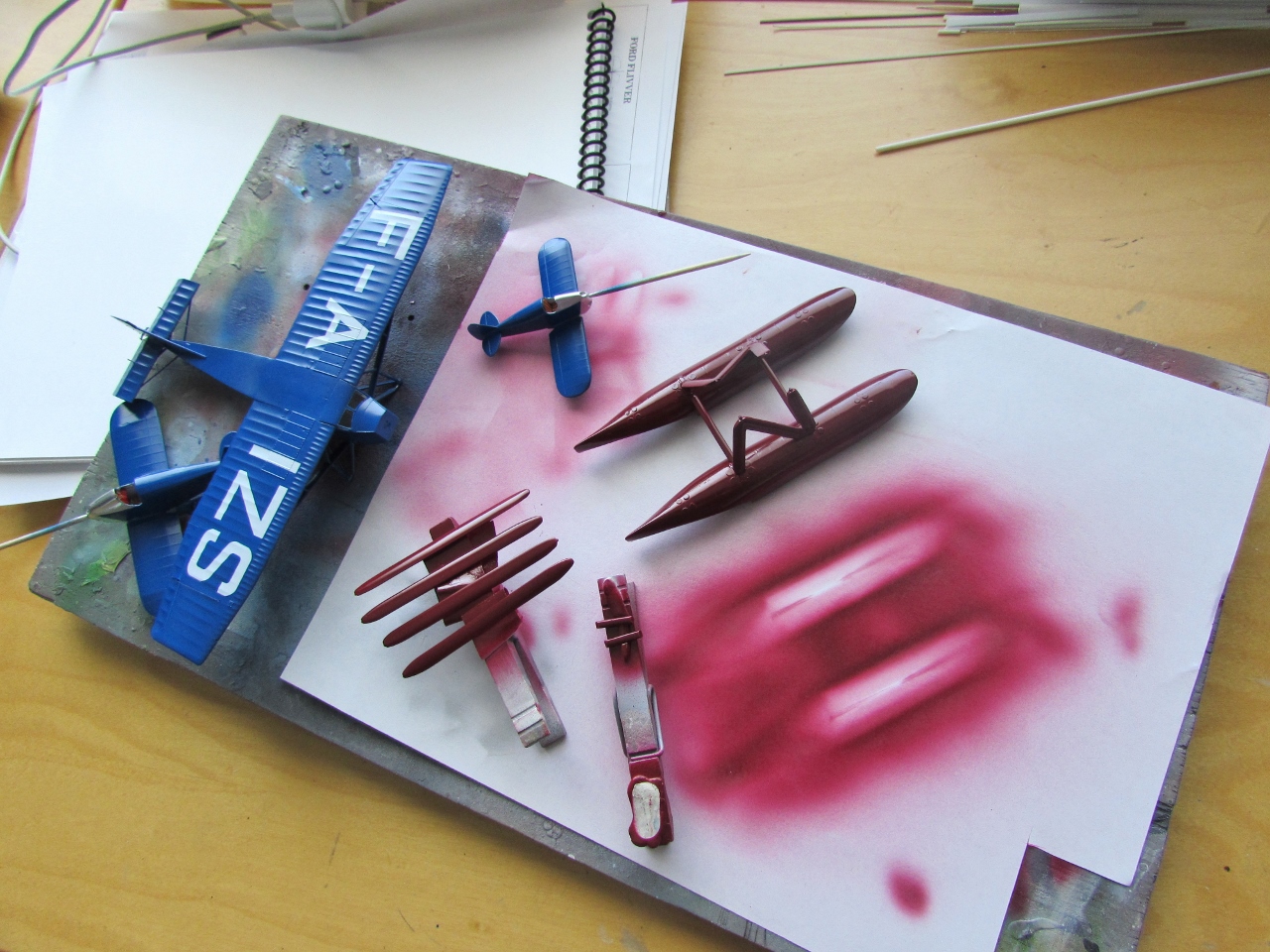
White is airbrushed over the primer. The upper half of the model is white. This will later be masked to apply the bordeaux color of the lower half of the plane:
The areas that will remain white are masked, in order to apply the burgundy color. The dividing lines passes through half the canopy height:
The burgundy color is airbrushed:
The photo-etched parts that make for the caps for the float compartments are discarded, since they are inaccurate in number and position. New ones are made of tin foil:
Then the floats are painted as well as all the other parts that needed their other side airbrushed.
The wood propeller blades are masked and their leading edge painted in metal to simulate the metal cladding:
The result:
Masks are removed from the model:
An Argentinian "ensalada rusa" is scratchbuilt for lunch:

All is ready now for the final assembly. I think I'll apply some decals before I join the other parts:
The scratchbuilt dolly is assembled and the floats tried on:
The dolly has been given a "dirty" wash and real rubber strips were glued to the surfaces that will be in contact with the floats:
The dolly will provide a more credible support to exhibit the model, instead of having to create a water display that sometimes tends to look not very realistic:
Application of decals under way. These decals are excellent, having very solid colors and being super-thin. On the other hand, they are very fragile, and will not tolerate mistakes and rough handling. Plenty of water, plenty of patience, do not let them fold on themselves and you will be ok.
A note: the vertical thin yellow lines are too short as provided. A spare small sheet came with my kit, most likely to fix that issue, but the lines are slightly broader. In any case, the lengthwise lines are exactly the required length on paper, BUT as they dry they contract a bit -as all decals, but you only notice it in the very long ones-, so more tiny bits need to be added to save the small gaps :
Decaling is completed. The floats are added, some rigging not indicated in the kit is put in place, then the wing struts and water radiator are glued, as well as the aileron linkages to the control horns. The drain tube of the toilet is also added:
Still to go: all control cables of the tail surfaces, the oil radiator, the photoetched steps and wind-driven generator, the lifting hooks, antenna, navigation lights, prop, doors, diagonal strut members, etc. etc.....
Modeling Theater Presents:
"Oopsy-Kaputsie"
A play in four acts
(I freaking knew I freaking had to freaking put freaking metal freaking pins in all those freaking resin freaking struts)
Ommmmm, Oooooommmmm.....There are no floats (The Matrix)....Ommmmm..
OK, metal pins for everybody:
Et voila. Fixed.
By the way, the instructions do not tell you that the cylinder covers should be black, and the thingy in the middle of them should be a different metal hue:
Only a few more steps (literally, the two steps on the right float front strut), the open doors and then the model will be ready:
Making the navigation light for the tail:
Drill a hole on a styrene rod of the needed diameter. Sand the tip round. Insert pin:
Cut off the tip. Prepare a segment of stretched clear sprue, or sand a clear rod to shape:
Cut the clear tip off:
Paint the solid portion and glue the clear tip:
Et voila:
To be continued....