
(This is the step-by-step building article and review, for the completed model please go here on this same blog:

Although not perfect (which kit is, anyway) this is a massive improvement over the old Frog -and Zvezda repop- kits, light-years away.
Thanks Valom for once in a while catering for that specific swath of demographics of the kit industry customers.
Thanks Valom for once in a while catering for that specific swath of demographics of the kit industry customers.
Long ago, the first thing that attracted me about models was
their aesthetics (I am an artist by profession), but modeling has later become
also a manual -as well as an intellectual- challenge.
I find myself immersed in joy tracking down the history and
details for a model as well as finding engineering (please excuse the term)
solutions for it.
It is nice to put a
kit together, pleasant and entertaining, but sometimes I want to know
more and to do more.
When the Valom Fokker F.VII started to come in civilized
liveries, I began to look at my references on the type and try to narrow down
the field to a few potential candidates.
I finally chose the Wilkins Polar Fokker F.VII
"Detroiter" and the Southern Cross (although I have an extensive list
of candidates now after quite some research). One plane in Alaska
and the other in Australia,
that were... the same plane! (in different times of its history).
Not only that, but for those who know that history, it was bought from and then
lent back to Kingsford-Smith by Los Angeles
resident George Allan Hancock, quite a character by the way, who lived nearby.
Connections are an interesting thing.
In any case, as the famous Southern Cross, it went through a
series of changes in appearance worth studying (if you care for such things). I
decided not to go for the usual and already many times represented plane as the
ocean-crossing one, but for a more appealing and complex livery it wore later
in time.
Now, as you enter the perilous and deceiving lands of
research, you will find the usual confusion and mislabeling and you will have to sort out the information with no little degree of healthy skepticism.
Anyways: the story of the Southern Cross is rich, complex,
long and fascinating.
I spend many pleasant hours searching and sorting. Do the
same if you care.
This "Southern Cross" version VALOM released is supposed to cater for the US registration 1985 (the plane for the well-known flight) and the plane re-registered in Australia as VH-USU. Thing is, as the fuselage is presented, it needs adjustments to represent them (because mainly of the doors).
Besides, VH-USU had a number or incarnations that involved very visible changes.
Strangely enough, you could build an authentic VH-USU plane, as it was in 1933 (or 1935 according to Getty Images) (The memorable ocean-crossing flight was in 1928) in the Australia to New Zealand flight, with both doors as the kit is, but using the three-blade propeller on the center engine, and different exhausts than the ones depicted in the instructions (the ones that go over the wing for the external engines and two long ones for the center one), plus shields on the engine fronts; all these details visible in period photos. Not sure the decals will perfectly fit, since the lettering suffered modifications during the plane's life, but you can potentially build a Southern Cross WITHOUT MODIFYING ANYTHING, BY JUGGLING THE EXTRA PARTS OF THE KIT AROUND, just not the plane depicted on the box. For that you need some work.
Once again, if you want an accurate model that faithfully represents the plane intended, you will have to gather references and check the kit against them. In this case, I recommend it.
VALOM as you will see provides a number of alternate parts to cover many versions, therefore you get some spares bin fodder.
This concept of a flexible building with alternate parts also helps modelers that want to build other versions not in the market, or planes that were modified during their lives.
On the other hand, to make several versions from one mold and added parts, they have made some compromises.
The instructions are in general reasonable, better than many, but still in parts confusing; to quote just two: the way the rudder bar and pedals attach to the console is unclear, and US-registered 1985 had no passenger interior but a huge long-distance fuel tank and some custom interior arrangement with radio and navigator station, a very obvious and known fact. VH-USU had seats only in one of its incarnation (the version highlighted above).
Since I am building the 1929 version of VH-USU that flew from Australia to Croydon, England, with a more attractive and less-known decoration (not presented in this boxing), the kit will need, besides a new paint scheme, a number of modifications, both internally and externally. The external mods have to do mainly with propellers, nose louvers, window on fuselage top, doors, side windows, and details like wind-driven generators and such, the internal mods account for the not standard interior.
So let's begin this winged journey:
This "Southern Cross" version VALOM released is supposed to cater for the US registration 1985 (the plane for the well-known flight) and the plane re-registered in Australia as VH-USU. Thing is, as the fuselage is presented, it needs adjustments to represent them (because mainly of the doors).
Besides, VH-USU had a number or incarnations that involved very visible changes.
Strangely enough, you could build an authentic VH-USU plane, as it was in 1933 (or 1935 according to Getty Images) (The memorable ocean-crossing flight was in 1928) in the Australia to New Zealand flight, with both doors as the kit is, but using the three-blade propeller on the center engine, and different exhausts than the ones depicted in the instructions (the ones that go over the wing for the external engines and two long ones for the center one), plus shields on the engine fronts; all these details visible in period photos. Not sure the decals will perfectly fit, since the lettering suffered modifications during the plane's life, but you can potentially build a Southern Cross WITHOUT MODIFYING ANYTHING, BY JUGGLING THE EXTRA PARTS OF THE KIT AROUND, just not the plane depicted on the box. For that you need some work.
Once again, if you want an accurate model that faithfully represents the plane intended, you will have to gather references and check the kit against them. In this case, I recommend it.
VALOM as you will see provides a number of alternate parts to cover many versions, therefore you get some spares bin fodder.
This concept of a flexible building with alternate parts also helps modelers that want to build other versions not in the market, or planes that were modified during their lives.
On the other hand, to make several versions from one mold and added parts, they have made some compromises.
The instructions are in general reasonable, better than many, but still in parts confusing; to quote just two: the way the rudder bar and pedals attach to the console is unclear, and US-registered 1985 had no passenger interior but a huge long-distance fuel tank and some custom interior arrangement with radio and navigator station, a very obvious and known fact. VH-USU had seats only in one of its incarnation (the version highlighted above).
So let's begin this winged journey:
Contents of the kit's box:


I would characterize this effort as meritory and valiant, but the results are mixed:


For some reason, the vertical stabilizer does not have an engraved separation line between fin and rudder. I marked and separated them:
 The doors have to be obliterated and a new one made for the special version I am modeling (and for 1985 and some of the VH-USU versions), besides toning down the surface detail. The front is masked to preserve it:
 Doors are filled with putty:
 Some parts not relevant to this version are separated and stored (not the horizontal tail, that stays):
 These are the engine gondolas needed for this version:
 The horizontal stabilizer:
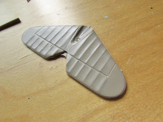 I separated the elevators to pose them more naturally:
 Some more parts for the spares bin, nice!:
 The internal structure reconstructed, but I will be using styrene rod instead anyway:
 The landing gear legs have a sleeve into which they run, but you will have to sand a bit the edges of the inner parts for this to happen:

 The doors were easily filled-in, and the somewhat excessive surface detail got much better with just a few passes of the sanding stick:
 The necessary Micarta props are fabricated using alu tubing and a couple of three-blade props that were just fine, being original wrong (that is, they rotated the other way, but fortunately for me, their pitch was reversely varied -that is to say they were wrongly adapted by the manufacturer from blades that rotated the opposite way, which suited me fine!):
 Stems are added to the cute blades -which retained their collars- to fit inside the tubes,. so the 2 three-blade props rendered 3 two-blade props, perfect!:
 Touches needed on the wing. That cut-out will show the -added- spar. Look at photos to see how the cut-out and windshield interacted before committing:
 Remove those ejector towers:

 The transparencies could be used to blank the area, but I decided not to, as the frames are different in this version. I marked the modifications on the parts:
 Then used styrene to blank the needed areas:
 The only (and different) door for this version is sawed-off:
 Door opened and styrene blanks in place:
 A door is cut from styrene to be posed open. Clear plastic will used to produce the necessary windows:
 The horizontal stabilizer is sanded down and rib tapes engraved lo lighten its appearance and match photos:
 Some structure is represented:
 The blanks for the window area are blended in:
 The opening on the lower wing:
 Ready to glue the wing halves:
 The home-made props are ready to paint:
 The kit's external panes of the windshield have to be cut:

 The tank long-range fuel tank in progress:


 The main interior parts ready to paint:
 Structure is added internally to the fuselage sides:
 The control wheels come positioned as "+" and have the column not behind them.
So they were cut from their stems, positioned correctly as "X" -which is their rest position- and provided a column behind them, as in reality:

 Some generic painting begins:


 That step to the cockpit has to go, since the fuel tank is now in that space:
 Dry run of the fuel tank:
 Some of the interior elements:

 A panel that goes on the tank face:
 Dealing now with the inst. panel. The quality of the P.E. fret is very good:
 The kit's wind-driven generators are not proper for this version, so I fashioned a couple (one per each side):

 Painting ensues as needed to create the necessary effect on the parts:
 Control horns are added:
 The completed inst. panel is ready to be added to the fuselage.
Wouldn't it be nice if the photoetched set would have a few freaking spares for those almost invisibly small parts? May be the ones that make them never build models, and if they do, never lose a part. I am like neither of those, heck, what is the cost of adding a couple extra levers?:
 Cockpit in place:
 Inst. panel in place:

 More details are fabricated, in this case the driver for the induction compass. The "flaps" are left long for easy handling, and are later trimmed down:
 The tripod-mounted compass:

 Preparation of the pee-pee device. As you can see it's hollowed, for the benefit of my Canadian friend Alain, who is very demanding regarding toilet accoutrements:

 The pee-pee device (I sometime make myself giggle) attached as per photographs:
 Another teardrop-shaped "thingy" (technical term that defines objects of unknown name and function) that goes on the fuselage top.
Here is a method I just concocted to fabricate teardrop parts:
1-Drill a small hole
2-Sharpen
 3-Cut
3-Cut
4-Reverse and insert the sharpened end on a tube of convenient diameter.
 5-Sand the tip round
 6-Insert metal stem, apply cyano glue.
7-Enjoy
 I did not use the kit's rudder pedals, since they are not correct for the civil version. Simple rudder bars were used, so those were fabricated and added. Also the "can" of the earth-induced magnetic compass was made and glued inside. I think we are now ready to glue the fuselage halves together, after adding the wicker chairs:
 Fuselage halves glued:
 Aileron horns in place:
 Holes are drilled on the wing for navigation lights, Pitot and aileron control leads:
 The broken pushrods and exhausts are easily replaced with stretched sprue and bent solder:
 The fuel tanks valve system that goes behind the pilots is fashioned:
 The engine carburetors, missing in the kit, are fabricated:
 The transparencies are fabricated from a CD case, something I learned from Lars Opland, of Khee-Kha fame:


 This Fokker had a belly, which slightly protruded from the otherwise flat bottom, so a scratched section was added:
 The seams in this kit needed some putty and sanding:

 The subtle new belly can be seen here:
 Chairs added:

 A last look before covering everything with the wing and say goodbye ;-)
 General view of the progress:
 Dry-run of the wing and stab to adjust their seating surfaces and get things leveled (the kit is especially not good at the stab insert). You can tell this model grows to a pretty size for 1/72nd scale:
 The carbs and upper struts are added to the engine gondolas, and the landing gear is assembled:
 Use the wing locating points to align the struts properly. Beware that the aft "V" struts are sided (asymmetrical), since their locating hole is displaced closer to the fuselage:
 The holes for the eyelet guides of the control cables are marked and drilled, 24 of them, with a fine bit:
 Size comparison with the ongoing Rohrbach Roland project:

 The tail is glued in place, with elevators deflected. Windows are being prepared for their insertion:
 After inserting and masking the windows and openings, the wing, engine gondolas and fuselage are primed:

 The primer revealed spots to be corrected -which is its function-:

 The aft "V" struts of the engine gondolas are sided, and have to be placed carefully using their location holes on the wing to adjust them while gluing them:

 All parts that will be painted aluminium color are given a gloss black base. The prop blades are painted a wood color, as per original Micarta props:
 The elevator control horns, very visible in photos, are absent from the kit, so they are fabricated. The wire you see is cut and the two horns are inserted from the sides of the cockpit in drilled holes:
 The dark blue that corresponds to this version is airbrushed over the fuselage, the fabricated door, the engine gondolas and ancillary parts:
 There is a piece of streamlined metal that will substitute the kits' plastic
parts that connect the fuselage with the engines, not accurately located
on the kit, which would have them attached to the bottom of the engine
fairing, when in reality they go a bit lower than that and connect to the carburetors -which in turn where missing from the moldings too-:
There is a piece of streamlined metal that will substitute the kits' plastic
parts that connect the fuselage with the engines, not accurately located
on the kit, which would have them attached to the bottom of the engine
fairing, when in reality they go a bit lower than that and connect to the carburetors -which in turn where missing from the moldings too-:
 Aluminium is airbrushed on the corresponding parts, big and small:

 Masks for the wing decoration scheme:
 Bottom:
 Top:
Top:
 Ready to airbrush:
 Airbrushed:
 Masks removed:
 Masks removed:
 Now the wing is in place, as well as gondolas and landing gear, plus windshield (which had to be tweaked for a good fit):
 Louvers are needed but missing from the kit, so Archer ones are cut to be added:
 Also an oil filling cap is added on the nose:
 To solve the issue of the guides for the external control cables I resorted to photoetched "eyelets":
 These were truly minuscule and a challenge to pick, dip the almost microscopic short stem in cyano glue, and insert in their holes:
 Phew! the first row of three!:

 Three rows now (there are four on each side, total 24 guides). Plus on the wing: fuel caps, fuel vents, four lifting lugs:


 A fuel pump -drawing from a wood casket- seen in one photo is duplicated:
 The home-made wind-driven generators -to replace the kit's, which were inaccurate:


The special interior in progress:

The fuselage top window area is cut out:


So they were cut from their stems, positioned correctly as "X" -which is their rest position- and provided a column behind them, as in reality:


Wouldn't it be nice if the photoetched set would have a few freaking spares for those almost invisibly small parts? May be the ones that make them never build models, and if they do, never lose a part. I am like neither of those, heck, what is the cost of adding a couple extra levers?:


Here is a method I just concocted to fabricate teardrop parts:
1-Drill a small hole
2-Sharpen

4-Reverse and insert the sharpened end on a tube of convenient diameter.


7-Enjoy


Threading monofilament through those minuscule eyelets was at the edge of my visual ability. One done, five more to go...:
 The manual pump is now ready to pose on the oncoming photos:
 The second control cable is threaded:
 And the third:
 The home-made wind-driven generators are glued in place:
 The navigation light, aileron cables and compass windmill are glued in place:
 The engines are added:
 All what remains to be added are wheels, props and decals:
 Decaling begins:
 The Pitot is fabricated:


To be continued.....