
https://wingsofintent.blogspot.com/2019/09/hadley-page-hp42-hercules-modified.html
I owe the pleasure of this kit to fellow modeler John Eaton, that very kindly let it go so I could have a go at this extremely exciting build. As we corresponded, John commented on what must have been to travel to exotic places on this gentle beast, in absolute luxury that only the well-heeled could afford.
As many of you know, there were in fact two of these Handley Page types, the HP42 and HP45, four machines
each. One covered the Eastern routes while the other covered the Western ones.
They differed on the powerplants and seat number and arrangement. Many other
external details varied from plane to plane too, so as usual photo references
are a must.
I have wanted to build this vacuformed kit for a long time. And
to think that I believed that I was handling a "big kit" and model
when I built this same manufacturer's Blackburn Kangaroo, but this behemoth is
far, far bigger, almost 55 ctms. in span (that is for you still leaving in the
dark ages about 21 1/2 inches). This design epitomizes "The Beauty in the Beast"
character that I so much love about vintage, Golden Age planes: ungainly,
preposterous, but ultimately irresistibly charming.
Through the years I gathered so much references on this
type, that only to go trough the graphic material takes me hours (I just did
it, again), not to mention the written portion of it that I leave for a rainy
day (or days).
The Contrail kit is not state of the art as we all know, but
I believe it will provide a decent base for a good model.
The kit , reputedly released in 1982 (37 years ago!!!) comes
with some goodies in the form of Aeroclub's white metal engines and four-blade
props, some airfoiled material, a metal rod for the landing gear, a few molded
parts (wheels and such) a cut of clear (now yellowed) plastic and some extra
styrene sheet. Accompanying the package are printed instructions, quite clear
for what I can tell at a glance, and clearly
printed reference photographs, not the fuzzy blackened photos much newer
manufacturers some times provide. A big decal sheet is also provided to cater
for (I think) every HP42/45. Not sure about how it survived the passage of
time, we'll see. This kit also provides a full interior, cockpit and cabin.
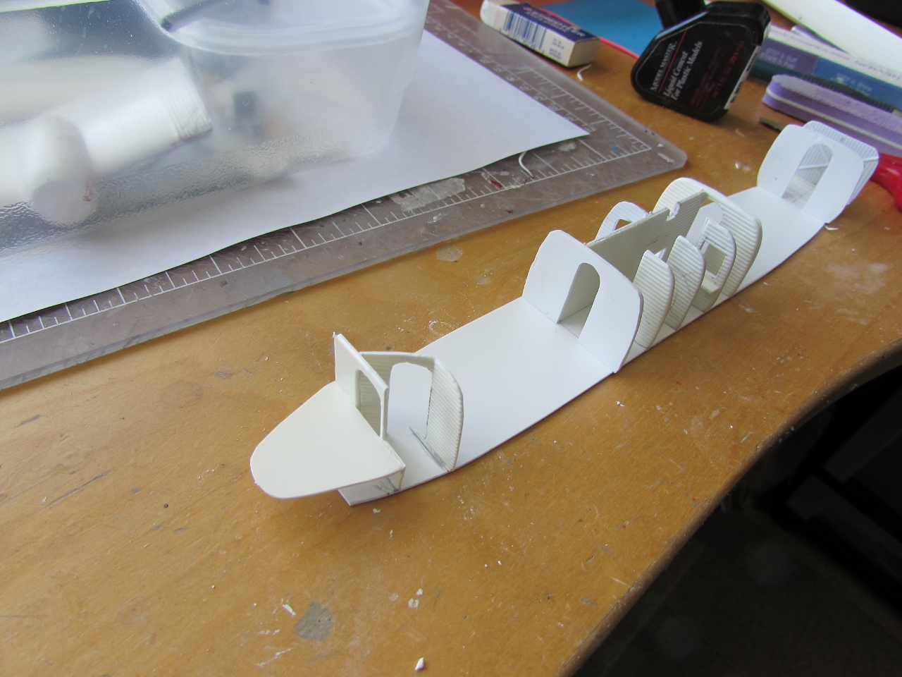
There is a particular piece of engineering in this kit, as
the cabin interior is eventually wrapped with a shell, which sides have the
curtains already molded in, and you have to cut off the "window"
area. That sub-assembly is later enclosed by the fuselage sides.
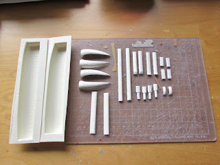
The monster kit:


As explained above, the kit gives the two seating options, eastern and western, with different cabin arrangements. Since I am not decided on which one yet, parts are separated for both:
 And in case you flop a corrugated part, know that styrene sheets with similar patterns are available in some model train and hobby stores:
 The fabrication of the home-made seats starts:


 My plan is not to replace anything that doesn't really need
replacement. I will work on the interior of course since it gives me
joyful and playful pleasure. I don't want to mess with the flying
surfaces (although I am tempted to replace those tail surfaces which I
can make in a snap and would look much better), and I don't want to mess
with the fuselage, other than adding the many steampunk thingies
protruding everywhere seen in many photos. I will replace the tail wheel
and associated parts, and perhaps the main wheels which look a bit off.
My plan is not to replace anything that doesn't really need
replacement. I will work on the interior of course since it gives me
joyful and playful pleasure. I don't want to mess with the flying
surfaces (although I am tempted to replace those tail surfaces which I
can make in a snap and would look much better), and I don't want to mess
with the fuselage, other than adding the many steampunk thingies
protruding everywhere seen in many photos. I will replace the tail wheel
and associated parts, and perhaps the main wheels which look a bit off.
I am also thinking (DO NOT TELL ANYONE ) of replacing the whole two sections of the front and aft window areas for strips of some sturdy clear material (since those two areas were flat, not corrugated), and just mask the windows, adding vinyl window frames in metal color. The frames as they are in the kit leave much to be desired, and I don't have photoetching capabilities, so the vinyl will be ideal (I have used "chromed" vinyl frames from the Arctic Decals set for my DH89 to great effect) That will eliminate the need of individual windows painfully fitted, and/or the dubious prospect of a clear strip behind the fuselage sides and that cumbersome "fuselage capsule" that the kit provides as a (literally in this case) convoluted solution (which I don't quite like).
So far my ebil plan.
As I look again at references (it's amazing how much is online readily
available) it's clear that apparently each plane had different
decoration solutions, and some photos even show seats with no upholstery
pattern at all, just plain textiles. Cabin trimmings vary too.
Beware that the photo in the (otherwise very nice) "Imperial Airways, The birth of the British airline industry 1914-1940" book by Robert Bluffield, that states that the interior photo is from "Hanno" is a mistake, since those are clearly the seats of the Short S.17 Kent, even if you can see a very deceptive tailcone structure behind the cabin. The Kent had it too.
So once more modelers and scholars are mislead by miss-captions -and I must say- some lazy research, since the seats of the HP42/45 had a very particular shape with the curvaceous double slope in the middle of the back support.
So once more: once you set on which of the eight planes you want to represent, bear in mind that interior and exterior details varied from plane to plane, and not only the two marks (42/45).
Speaking of windows, the kit has a flaw in that regard, since it positions both window rows in the same baseline, which is incorrect, since photos and factory drawings clearly show the aft row "rising" a bit, to better accompany the cabin floor angle upwards towards to the tail:


 And the allotation of seats is completed:
 Bad (but predictable) news, the protective paper of the decal sheet fused on, after almost four decades, so new ones will have to be commissioned:
 Not even in water the protective paper will let go of the decal, that otherwise is completely ok:
 Funny that the decal did not shatter or broke down, it is perfectly ok on the other side as shown, but the protective paper is firmly glued on the front:
 Some parts are separated from the backing sheet. Notice the small parts still on a scrap, those are the two odd seats that are located back to back to the cockpit bulkhead, and where smaller. Needless to say they need to be replaced (only for the "high density" configuration):
 The size of this giant is made evident by the comparison with the in-progress Caudron C.366:
 A hair was embedded in the plastic, most likely a wholly mammoth hair, given the age of the kit:
 The molded items are coarse and their mold halves mismatched, sanded equal here:
 The tail components are liberated. Absolutely unnecessarily thick, which will make their thinning a sanding nightmare. Why the manufacturer put this parts on the very thick sheet and not with the thinner "capsule" parts will remain as another kit industry mystery that not even Poirot could solve:
 More elements are extricated from the backing sheet:
 Still more to go:
 The remainder of the parts is freed.
It is of note that through a molding trick, the slats and top wing wing leading edges curve down and in, in what is called an undercut, not easy to achieve on a single mold, but if you do it only in one way, you can pull the molded sheet first a bit to one side liberating the undercut and then up. Clever.
I did not bother with the capsule since at this point I don't think I will use it:


I am also thinking (DO NOT TELL ANYONE ) of replacing the whole two sections of the front and aft window areas for strips of some sturdy clear material (since those two areas were flat, not corrugated), and just mask the windows, adding vinyl window frames in metal color. The frames as they are in the kit leave much to be desired, and I don't have photoetching capabilities, so the vinyl will be ideal (I have used "chromed" vinyl frames from the Arctic Decals set for my DH89 to great effect) That will eliminate the need of individual windows painfully fitted, and/or the dubious prospect of a clear strip behind the fuselage sides and that cumbersome "fuselage capsule" that the kit provides as a (literally in this case) convoluted solution (which I don't quite like).
So far my ebil plan.
Beware that the photo in the (otherwise very nice) "Imperial Airways, The birth of the British airline industry 1914-1940" book by Robert Bluffield, that states that the interior photo is from "Hanno" is a mistake, since those are clearly the seats of the Short S.17 Kent, even if you can see a very deceptive tailcone structure behind the cabin. The Kent had it too.
So once more modelers and scholars are mislead by miss-captions -and I must say- some lazy research, since the seats of the HP42/45 had a very particular shape with the curvaceous double slope in the middle of the back support.
So once more: once you set on which of the eight planes you want to represent, bear in mind that interior and exterior details varied from plane to plane, and not only the two marks (42/45).
Speaking of windows, the kit has a flaw in that regard, since it positions both window rows in the same baseline, which is incorrect, since photos and factory drawings clearly show the aft row "rising" a bit, to better accompany the cabin floor angle upwards towards to the tail:


It is of note that through a molding trick, the slats and top wing wing leading edges curve down and in, in what is called an undercut, not easy to achieve on a single mold, but if you do it only in one way, you can pull the molded sheet first a bit to one side liberating the undercut and then up. Clever.
I did not bother with the capsule since at this point I don't think I will use it:

Instead of providing a cohesive body of notes regarding the many aspects of the build (historical, technical, sociological, psychological, political, culinary and the like) all that is needed in one place, I decided to just sprinkle them here and there, which is immensely more fun and utterly impractical.
So here we start:
-The tail fins do not conform to upper stab intrados as the kit and many models present it, but are slightly separated and pinned.
-Early Hannibal shows additional diagonal strut at the wing tip (later replaced by cross wires), and small stab trim.
-Extra cargo door on some on the aft right fuselage after corrugations (not on Horsa or Hanno)
-Two finned oil coolers on diagonal struts upper engines (among the myriad of gizmos that bristle all over the surface of the planes)
-Photos show the same plane with and without nose light (Hengist) or superimposed two two-blade props and four blade ones (some of the rest).
-The lower wings have a corrugated area at their roots. Those are not to be butt joined without alteration to the fuselage, but have to be altered to partially conform to the fuselage contour as shown in photos.
All models I have seen have it just butt-joined without alteration, which is inaccurate and also slightly alters the span, augmenting it:


It's only occasionally that the goddess fortune will smile upon the modeler, but today is one of those occasions. I found good wheels to replace those not so convincing from the kit. IIRC, these came with a flying model, bless their balsa wood:
 A quick rummaging through the spares produced suitable cockpit seats, some potential pantry and radio elements, possibly a support for the instrument panel, and a couple extra parts to remind myself of things needed (oil coolers, for example).
No weekender, this one:
 Some bulkheads require a double corrugated surface, so they are glued to similarly-patterned styrene sheet:
 Sanding begins, and then goes on, and then goes on, and on, and on...
 Reducing the thickness of the part on the left to the one on the right:

 More sanding ensues. If you dpon't want a clunky-looking vac, you have to put some effort in it. I remind you that you start with this:
 And you have to get to this:

 This -that loose sort of filament- usually gives you the clue that you are about right:

No weekender, this one:


The double-faced bulkheads are ready, and some of the other elements have been sanded already too.
Stabs and vertical tails are united:

I decided to replace the rudder servo tabs, since the kit's, a bit chunky, wouldn't really do:


The suggestion of the kit to glue the vertical surfaces to both stabilizer surfaces is inaccurate. It took many photos and a couple of diagrams to figure out how all works. Besides, as time went by the manufacturer introduced visible changes (horizontal servo tab ahead of the upper stabilizer or not; no bracing, two braces or four braces holding the upper stabilizer from the central fin, etc). The vertical surfaces were "glued" only at the bottom, and have quite a gap at the top, slanting backwards. The incidence on the top horizontal stabilizer is less than that of the one at the bottom (something also commonly seen in biplanes).
Accordingly slots are carved, holes drilled and metal parts inserted, besides adding the anchoring pins:


I wasn't satisfied with the kit's floor and floorplan, so I cut a new floor from styrene sheet and adjusted the locations of dividers according to another source. Besides, the same way I doubled the bulkheads with corrugated styrene where they may be seen that way from both sides, I added smooth styrene to the smooth side of the bulkheads that face the cabin, since the cabin side of those bulkheads wasn't good enough:


The reading and processing of the reference material is on itself a monumental task, but none well worth the effort, as you discoverer so many useful things. Today I discovered that there was a service window between the steward compartment and the bar, exactly as in a bar, so to speak, so I removed the pertinent partition and practices a window, and made the seats for the passenger bar, together with the toilets, that you may need after you have visited the bar, and especially if the flight was bumpy:

One of the considerations is of course as usual how much of all this will be seen. We know the answer: almost nothing.
But we can help some times: I noticed that there is a hatch that communicates the cargo haul with the mid-section hallway, and since I plan to open the external cargo compartment door, I can leave the hatch open and therefore provide a glimpse at the bar! mind you, just a hint, but hey, a welcome one since the effort is made anyway.
This is all so much fun!
Some after-market trunks are separated for later use:


The inaccurate sections are excised:


The shells will be now fragile and very flimsy, and extremely prone to crack at the least provocation, so this is no time for katana shenanigans alla Kill Bill:


And whatever is that little square bit after the hatch (also part of the inaccurate spine?) has no correlation in reality that I can tell:


I may leave the hatch out, as during refurbishing or maintenance, to grant more visual access to the interior:


You are supposed to do this:

But the vacuum draw of this feature has created a thin and very fragile leading edge that came pre-craked on my sample:


Bear in mind that if you want to cut free and use the slats deployed (I will) you have to deal with that avoiding the reinforcement there:


I am not particularly fond of the engineering solution in this kit:


The instructions, now that I am paying more attention to them, are almost laughable and of course fuzzy and uncertain (the spar for the lower wing comes to mind), as it seems to be the tradition on kit-making, with very few and honorable exceptions:


Then superglued to the top upper wing:


The bright side of this is that in committing to do some research for my modeling projects, I discovered a universe of history, engineering, wonderful anecdotes and the incontrovertible fact that many things that are considered true are Mickey Mouse fantasies, blatant generalizations, bogus assumptions and hand-me-down misconceptions.
Research has become for me entertaining, exciting and pleasurable, not a duty or a burden.
And speaking of which: on this photo I found two small auxiliary struts, that are seen in only some of the HP42/45, and not consistently on the same machines through time. Visible on this image is the only roof feature, a vent, instead of the truckload of tin cans and intakes, outlets and such normally seen in this area on HP42/45s.
Of note is that the circular porthole in the area of the ladies washroom appears partially covered in many planes, or later on time on the same plane, no doubt to preserve the ladies from the curiosity of...birds? stowaways hanging from the wing struts?, hum perhaps from indiscreet sights form the maintenance crew during pit stops...ah...an euphemism, in the case of one of the sides of this story.
Study your subject...and study it along its lifetime, things may change...

The area behind the slats is filled with a "ribbed" piece of styrene:


And what do you know! here too, there are discrepancies between the two lower wings, some marks being 2 and 3 millimeters out of place.
While you check this on yours (if you happen to build one), bear also in mind that the distance between struts (fore and aft) is bigger in the upper wing that on the lower wing.
Hence new holes are drilled and the old elegantly plugged with some styrene rod:


The upper wing engine gondolas are attached. Their fit has to be adjusted:

Assembling of the tail begins:

Assembly of the tail continues, and the tail wheel complex is under way. The kit's tail wheel is inaccurate both in shape and size, so it's replaced, as were the main wheels. Furthermore, the injected parts in the kit associated with the tail wheel are laughable miseries, and were mercilessly thrown in the trash can:

I finally decided which registration the model will bear (a secret for the moment). Consequently, since that registration had the aft cargo haul, and the kit presents none, the door is drawn with pencil and the part excised, carefully. The actual door did not look like the removed part (it was smooth and had structure behind), so a new one will have to be made to replace it:


The new cargo haul door is made:


The additions are checked as always with yet another dry fit:

Holy corrugations, Batman!

Almost every model I have seen so far made form this kit presents a problem regarding the insertion of the lower wing in the fuselage. It is usually solved with a flat butt joint not shaping the corrugations on a curve, but that's not how things are in reality. The issue is that the kit's fuselage cross section is (surprise!) not very accurate, and it's more boxy (squarish) than it should be. The drawing bellow shows the differences with some exaggeration -but not much-, to make the point:


This means that some complex shaping will have to take place on both lower wings to accomplish a realistic joint, plus meet the spar, plus achieve to be symmetric to the other wing, in all axis. Trembling and biting nails yet?
The cockpit/radio area is a bit vague in the instructions, and does not match well with I can see in photos. This assembly is a bit provisional, so I can put it in place and see how things work. As usual, the side of the kit parts that face the cabin should be smooth (the kit's parts show a wobbly surface product of the corrugations molded on the other side) and a doubler has to be glued on. The cockpit floor is oversized and will have to be trimmed back:


Several ebil plans are taking form.
To start with, there is no problem with normal modeling on shaping and thinning the plastic, it can be brought to adequate gauge sanding the corrugations on the wing root from underneath, and the rest of the root can be carefully conformed to the fuselage shape (besides the fuselage area that it will cover could be lightly sanded a bit):


Just in case, I pulled from the bottom of the magic drawer some corrugated aluminium sheets I bought about 12 or 14 years ago. One has its label, the other I have no idea of the brand. Both were bought from model train stores that are no more (like all the hobby shops that were in my area). This in case I need to change the plan and use something like that:

Preparing the spar and sleeve of adequate size:


Another approach will be to remove the whole area and build the glazing up with clear material sections, or carve a master and vac the glazing. I have done all of these in other models, but here, given the astronomical amount of work still needed in this model, I will keep it simple.
All the openings that can or need to be practiced are already done:


Now it's the turn of the landing gear. The metal rod provided with the kit is too big and can't, in any way, be wrapped by or inserted in the leg parts provided. Yet another aspect of kit fantasy here. There are two solutions: to make the "wraps" in embossed styrene and keep the thick rod or to get another, thinner piece of metal, which I did, with some brass "Strutz".


https://www.youtube.com/watch?v=Q6CeQiXHlAU
https://www.youtube.com/watch?v=8kuDb9h_b9M
Meanwhile, the masks and frames arrived from Arctic Decals:

Now that I have gotten the masks, the transparencies are are carefully glued:


I asked my British wife if she would use the brand of hygienic paper suggested here by some members, and she blanched and was outraged. She said it was unladylike and ungentlemanly-like. So my passengers will most emphatically be using toilet roll, which I added too, and thank you very much but you can keep the creased sandpaper called Izal to yourselves as used in your flying saucers, offices or schools. My passengers were reputedly paying the equivalent of 20,000 pounds for the longest trips, so I think they deserve at the very least the courtesy of civilized toilet rolls, even if they lack bidets, which is on itself a scandal and not at all posh:


The fuselage is finally put together, a nerve-wracking business:


State of the union:


More little blemishes are corrected:


We have determined early in the build that the lower wings DO NOT butt-join the fuselage on its sides where it's flat, but instead the top skin mounts over the fuselage top in the shape of an arc (as photos of the original plane show), and the bottom of the lower wing is what touches the fuselage side.
This implies adjusting the root to a complex and changing shape, not to mention that the wing has also incidence.
I devised previously a spar-and-socket anchoring method, and now have to adjust both wing roots in all axis, as I install the sockets inside them with epoxy.
Bellow you can see the hole where the spar will go:

Again, this is by far the most sensitive part of the building. Not only that, but butt-joining as the kit suggests displaces the lower wings by a whole centimeter out, producing -down the lane- strut geometry issues (since the lower wing span is inaccurately increased):


The model is now ready for basic painting:


I can't even begin to tell you how happy I am:


The first areas to by dealt with are those highly-reflective ones, that later will be masked to proceed with other tones of metal:


The tail is ready for its rigging, and now the monoplane is getting close to its final stages:


In my thermoluminescent and unfathomable wisdom I realized
that, contrary to custom, in this particular case, decals should be applied
before final assembly and detailing, considering how magnificently encumbering
will be trying to operate the lumbering giant once finished, turning it this way and that, with all those
prickly and delicate things and its massive bearing:


And better do the same with the tail unit:
 The tail unit is glued to the fuselage:
 The engines of the upper wing are glued on, their exhausts anchored. Their positions (asymmetrical) are mirrored, the right engine (viewed form the front) external exhaust coming from 4 o'clock relative to the engine, and the internal at 10 o'clock (i.e. the internal pipes will be shorter):
 The heat exchange sleeves (mirrored) for the external exhausts of the lower engines are fabricated. They will be painted, anchored to the nacelles, and then the pipe coming from the engine inserted:
 The plumbing for the lower wing engines exhausts is in place now:
 A small hatch on the fuselage side and what looks like some drainage below the restrooms area are added:
 Before proceeding with the final assembly, more decals are added and other details added in hard-to-reach areas:

 The cargo hatch and the brake wires are added:
 The decals from Arctic Decals are very nice indeed:


A major build landmark was reached today, the upper wing is finally on:
 Only the external struts were glued, the rest will be inserted gradually mirror-fashion, checking that no distortions are induced, and adjusting lengths as (and if) needed:

 With each pair of struts the whole becomes more rigid.
I twisted myself and contorted so amazingly to put those struts on that I could work on a circus:
 I knew, as I was taking measures from the plan to make the struts, that their relation to reality (i.e. : the model) would be vague, to put it mildly, so I made only a partial set, and left the rest for now, that the first group is in position, to take measures directly from the model in order to make the remaining eight struts the right length. Here are a few (on the desk, to the right of the model):
 The remaining struts being painted:

Almost all struts in place, only missing the diagonal in the engine area:


I twisted myself and contorted so amazingly to put those struts on that I could work on a circus:


To be continued...