

(for the completed model, please go here:
Thanks Mikro-Mir for this and other civil releases of
unusual and delightful planes!
This Miles Aerovan cute kit of a cute plane is in line with
the latest kits that Mikro-Mir has been introducing to the market. A fair
price-quality ratio, appealing subjects, good engineering and nice moldings
with plenty of detail, including even the masks for the transparencies!
I have had a folder on the Miles Aerovan for ages, and waited for a kit -against all chances- instead of scratchbuilding it, paid off.
Who says dreams don't come true sometimes?
The variant released by Mikro-Mir is the IV (fourth), and includes several liveries in its decal sheet. But if you -like me- you tend to diverge and follow your own path, there were other many liveries out there. Just be careful to see if they are the right variant, and not the ones with different windows or engines. Some adventurous modelers may even convert this kit to those other variants, perhaps the most extreme of which was the Hurel-Dubois/Miles HDM 105, with a high aspect ratio wing.
The variant released by Mikro-Mir is the IV (fourth), and includes several liveries in its decal sheet. But if you -like me- you tend to diverge and follow your own path, there were other many liveries out there. Just be careful to see if they are the right variant, and not the ones with different windows or engines. Some adventurous modelers may even convert this kit to those other variants, perhaps the most extreme of which was the Hurel-Dubois/Miles HDM 105, with a high aspect ratio wing.
In any case, you also get a fully detailed interior, nice
for the scale, but beware that some variants used the cabin as cargo hold.
Photos show one even loaded family cars! Another of them had installed neon
signs for night flying.
In any case, what an interesting and well-produced model.


The major parts are liberated from the sprues:
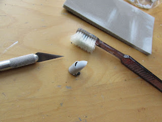
 And then the smaller parts. Do not do this if you don't have enough experience, you will miss or get confused with the parts. No sprue cuter will do this, especially with the more fragile parts, like seat frames, molded delicately, so I used a razor blade. Tape one end to protect your finger:
 My impressions on this kit continue to be very good:
 Assembly of the rather fiddly seats begins:
 They are nice, because they surely have a scale appearance, but they are not easy to assemble:
 Each has five parts:

 The seats are ready, and other cockpit sub-assemblies are finished too (pilot's seat, side console, front console):
 More sub-assemblies in progress, this time fuselage-related:
 Engines follow:


 Wheel halves cemented:


 Second panel goes on:
 I know very little about kit manufacturing, but why the master maker (or, more unfortunately, CAD person) did not make the parts' separation where the hinge line is (or the curve in the case of the flaps), instead of in the middle of the panel, that now has to be filled in and sanded?:
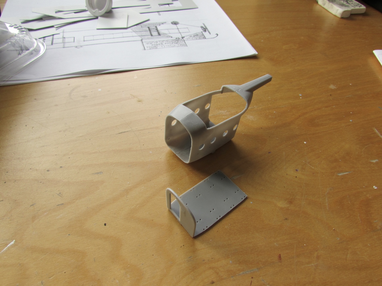
 The aft structural part that attached to the fuselage "node" is angled as it comes. Drawings show it to be flush with the top, so I sanded it to correct it:
 There is no side drawing to show the real angle of this part:
 Here is what I did, hoping I am right:

 The engine nacelle is comprised of two sides for the shell, a pan, a front "fake" part and the nose:
 The front "fake" part looks odd, will be mostly hidden, and doesn't really reflect reality:
 There is a light case that goes on the front of the cockpit assembly. I hollowed it:
 In order to add an MV lens for realism:
 Position of the light case:
 The engine nacelles interior is painted black and drybrushed:

 An air exits are carved:
 A swift pass on the sanding block revealed that the halves of the horizontal stab were not true, so more sanding (and thinning) was necessary):
 It would be wise to drill those locating holes for the central fin, since they do not go through in the part as molded:
 Now that's better:
 The box inaccurately depicts the central rudder as going over the elevator:
 It doesn't in real life:
 Beware that the central rudder was balanced. The kit depicts the rudder with both lines, for some reason:
 The kit maker forgot to depict the elevators as independent units, therefore a line is engraved following plans and photos:
 Horizontal stab halves ready to be glued:
 The dividing line is of course engraved in both sides:
 Horizontal stab glued, associated parts in the photo too. The tail cone as molded has a seam that may need erasing:
 There are very nicely molded tiny parts, like the Venturi, for example, seen in this sprue:
 It's always difficult to properly clean minute prop spinners of their attachments to the sprue...
 ...so I make my own:
 The wing halves seam underneath is puttied and sanded:
 The aileron hinge, solid in the mold, is drilled to match photos:
 I decided to glue the fuselage sides together, having realized that the interior can be slide in easily:

 This was fortunate, because I realized that, as the aft part, the fore part of this assembly "natural fit" was wrong, being the angle down too much pronounced:
 Original, natural fit angle:
 Detached and re-glued to the correct angle:
 With good fit now:
 The nacelle sides have an airscoop on each side, but only one is correct:
 The tadpole body:
 The cabin slid in, and related parts:
 The wing fit is fair, but needs some adjustments (dry run):

 The engine nacelles are glue on the wing. They need adjustment to properly fit:

 Making sure that the spine will go comfortably on once the wing is glued (it isn't yet):
 It does fit properly:
 Parts are prepared for painting:
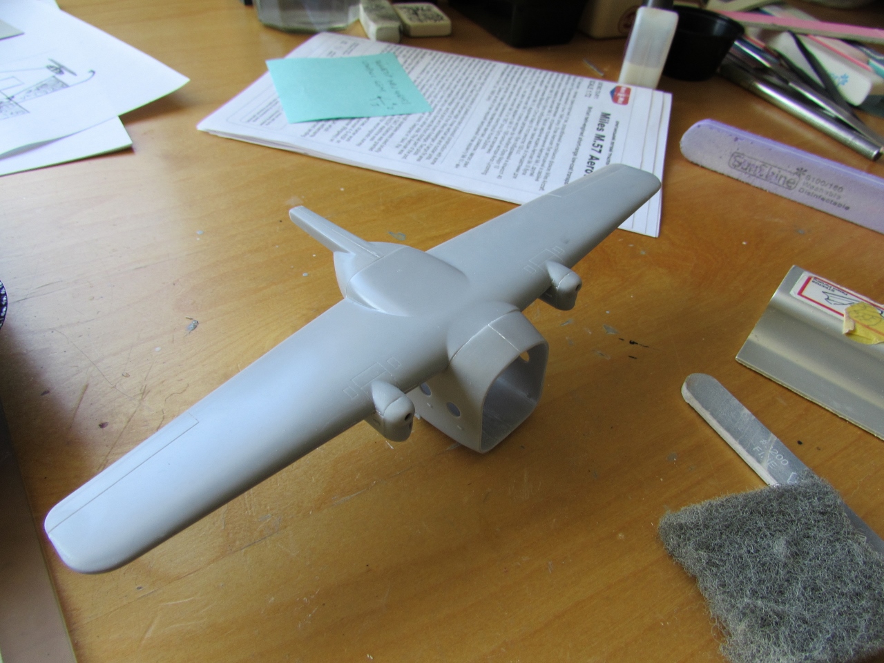
 A neutral grey is airbrushed in order to be able to proceed. Details will be added and painted, windows will be glued from inside:
 The clear nose parts had some little flash that was cleaned. The two halves didn't match exactly, so two clothespins were used to keep the upper and lower edges aligned while the glue dried:
 The spine was given some rivet impressions:
 A little strip of styrene had to glued to pack the edge, since the lower edge has to be sanded to match the clear nose:
 You can see here the small difference at the bottom:
 The fuselage was carefully sanded and now we have a good match:
 Spine painted:
 The clear parts are given a bath in acrylic floor polish
 The nose of the cockpit had to be sanded down carefully, or will hit the clear nose and preclude a good fit:
 Nose parts also bathed in acrylic:
 I lost a couple parts from a seat, so I had to reconstruct them:


 The seats are painted:
 Lacking the necessary references to build the photo version, I will have to go for one of the passenger versions, therefore the seats are added:

 Photos show a resting part for the aft floor, so it is replicated and glued in place.


This added styrene parts will be painted in situ. The windows are already glued:

The interior is glued:
 The the spine is added:

 Once the spine glue is almost set, the wing is tried on, just to be sure that there are no glitches:
 It is likely that I will pose the tailcone open, so the two parts that
you normally glue to the fuselage -if you want the tail closed- are
glued to the tail:
It is likely that I will pose the tailcone open, so the two parts that
you normally glue to the fuselage -if you want the tail closed- are
glued to the tail:
 The exposed areas are therefore painted:
 Looking now more closely -as completion approaches- the possible
finishes, I call into question the livery on the instructions for
PH-EAB.
Looking now more closely -as completion approaches- the possible
finishes, I call into question the livery on the instructions for
PH-EAB.
I found online six different photos of PH-EAB, none of which coincides with the drawing on the instructions.
To start with, horizontal tail and wings have colored leading edges, absent in the drawing. The drawing suggest (no top view, though) that the blue color wraps around the wing on the fuselage, which is inaccurate.
All photos show the blue stopping at the leading and trailing edges of the wing. Use a search engine with "PH-EAB" on the images tab and you may see some of these photos.
I am making a note of this in case somebody (or myself) goes for this color scheme:
 You may also notice that in the drawing above the nacelle of G-AISF
(top livery) is not shown as red to the right on the top and bottom
views of the wing.
You may also notice that in the drawing above the nacelle of G-AISF
(top livery) is not shown as red to the right on the top and bottom
views of the wing.
The wing is shown below already glued in place. The seams will need a bit of care:

Well...further questioning the liveries in the instructions, I found a photo of G-AISF that shows it was cream (as I assumed earlier on the thread for some liveries) and green, not grey and red.
The photo can be found in this thread (I found the thread googling for the registration):
https://brexitmodeller.com/forums/topic/1486-mikr-mir-miles-m57-aerovan/?page=2
 Whaddayaknow
This reminds us all not to blindly trust all we are told.
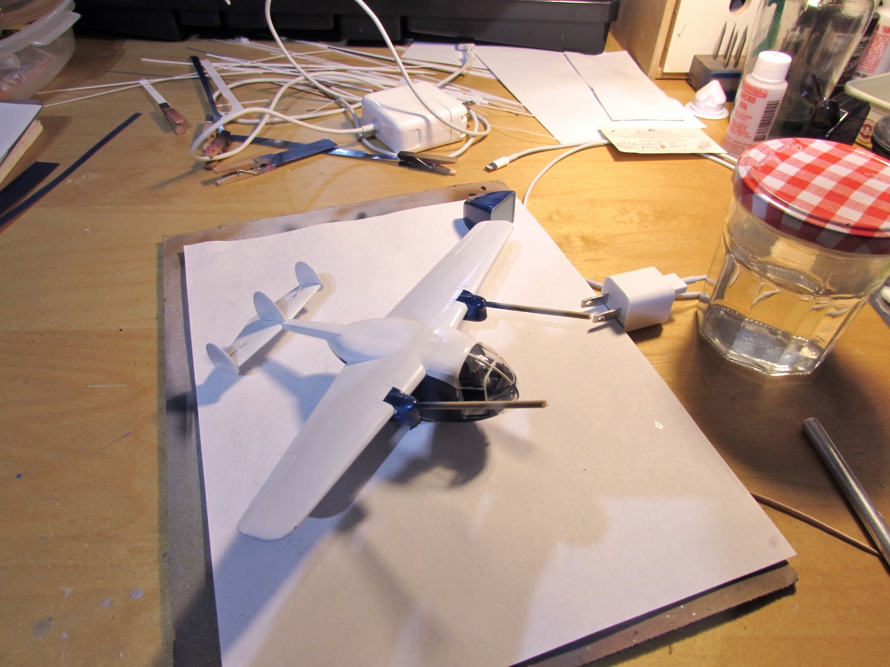
This is a tail-sitter, so weight has to be added at the cabin front bellow deck, of on the nose where is not visible (the model is rolling back on rod placed at the main LG):
 And the messy part begins...

 I am preparing the weights, which will probably go on the nose bellow deck:
 Weight is added to the nose as seen here. A number of pieces were needed to get the plane to be nose heavy. The kit's windows' masks are in place. The central rudder has that inaccurate vertical tip line puttied:
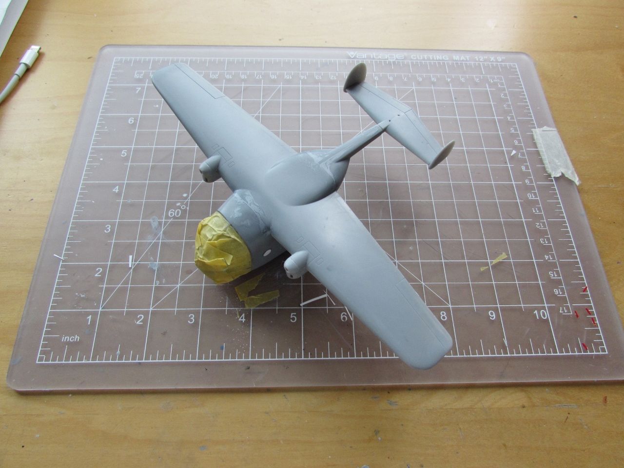
 The clear nose is glued and taped in place to allow the glue to set:
 Once the nose is secured, it is masked to expose the frame in contact with the fuselage for its blending:
 The Canyon fire smoke over the Pacific, today, 10/9/17:


I found online six different photos of PH-EAB, none of which coincides with the drawing on the instructions.
To start with, horizontal tail and wings have colored leading edges, absent in the drawing. The drawing suggest (no top view, though) that the blue color wraps around the wing on the fuselage, which is inaccurate.
All photos show the blue stopping at the leading and trailing edges of the wing. Use a search engine with "PH-EAB" on the images tab and you may see some of these photos.
I am making a note of this in case somebody (or myself) goes for this color scheme:

The wing is shown below already glued in place. The seams will need a bit of care:

Well...further questioning the liveries in the instructions, I found a photo of G-AISF that shows it was cream (as I assumed earlier on the thread for some liveries) and green, not grey and red.
The photo can be found in this thread (I found the thread googling for the registration):
https://brexitmodeller.com/forums/topic/1486-mikr-mir-miles-m57-aerovan/?page=2

This reminds us all not to blindly trust all we are told.
This is a tail-sitter, so weight has to be added at the cabin front bellow deck, of on the nose where is not visible (the model is rolling back on rod placed at the main LG):


The back is covered and sanding of the putty begins:

 The tail is glued on, minus central fin:
 The seam will be treated next. Isn't it a cutie? Oh, coochee-choochee-coo:
 Central fin is glued and a coat of white primer goes on, to spot blemishes and correct them:
 Managed to squeeze-in another half hour.
The Pitot, flap rails and elevator balances are in place:
 The kit mudguards are a tad thick, you can either sand them down on a
round form, or make new ones from bent styrene sheet cut to size:
The kit mudguards are a tad thick, you can either sand them down on a
round form, or make new ones from bent styrene sheet cut to size:
 The area where the oleo strut goes is too flat and the relief is not enough to hold the part securely; and the hole for the landing gear leg too shallow:
 The oleo strut contact area is modified to a good contact can be achieved. The hole for the leg is deepened:
 Legs in place. The location of the flap actuator is also drilled, again for a more positive contact. The two parts that constitute the aft cone lock are glued in place, properly aligned:
 New navigation lights are fashioned from clear sprue and tinted. Their locations are drilled on the leading edge:
 The provided masks proved to be a bit of a disappointment. They are not
really precise nor accurately follow the surfaces. They are too rigid
for the compound curves, therefore they will lift front the surface at
stress areas.
The provided masks proved to be a bit of a disappointment. They are not
really precise nor accurately follow the surfaces. They are too rigid
for the compound curves, therefore they will lift front the surface at
stress areas.
There are no instructions for them, where they go, or numbers. But it's not hard to figure that out -after some head-scratching, though.
You may need to carefully slit them to make them fit properly.
Still, bad masks is better than no masks at all, and they provide a starting point. I had to supplement with Tamiya masking tape to render accurate edges and to "patch" the areas where the kit masks overlap, since they kept lifting too there.
They are kind of sneaky, and may remain attached for a while, but then they will eventually unstuck in places (the surface was clean, by the way, and my fingers were not oily, so we are clear on that) so give them a thorough inspection before airbrushing:
 Since I plan to pose the door open, an inner window "counter-mask" is
fashioned and attached, allowing for the painting of the interior color.
After painting, the handle detail will be hand-picked:
Since I plan to pose the door open, an inner window "counter-mask" is
fashioned and attached, allowing for the painting of the interior color.
After painting, the handle detail will be hand-picked:
 A touch-up with more primer in the areas that have been re-worked, and hopefully when dry it will be ready for the base paint (white in this case) and then -after masking- the second color, blue:
 Ancillary parts like props, exhausts, spinners, door, are painted on their respective colors:
 One of the masks -for the left window- detached. I had to make another from Tamiya tape:
 Thew white paint is airbrushed. Props are masked to paint the yellow tips:
 Spinners are glued in place:
 Masking the flying Easter Egg. I reiterate that the painting scheme in
the instructions is not accurate and doesn't correspond with reality,
being that for PH-EAB and most of the other schemes, so, once more,
check your photos:
Masking the flying Easter Egg. I reiterate that the painting scheme in
the instructions is not accurate and doesn't correspond with reality,
being that for PH-EAB and most of the other schemes, so, once more,
check your photos:

 After the application of the blue color and acrylic overcoat, the masks are removed.
It pains me to report that if so far I have considered the kit's masks inadequate, now I have downgraded them to quite problematic.
If at the beginning they kept detaching, after a few days they were cemented to the canopy. As a fellow modeler commented above, they do leave a residue sometimes, and they get so completely stuck that while you are removing them you become terrified of yanking the clear nose off.
This nice kit deserved better masks. The provided ones are clearly deficient.
Now I am in process of carefully removing the residue.
You may notice, as explained before, that I am not following the kit's depiction of the color separation scheme, since it is frankly bogus on the instructions:
 Painted and cut to size decal stock is used to simulate the leading
edges of wing and stab visible in photos. The setting solution is still
at work:
Painted and cut to size decal stock is used to simulate the leading
edges of wing and stab visible in photos. The setting solution is still
at work:
 A few touch-ups will be needed. The emergency exit on top was simulated with a section of white decal stock:
 Here working on the underbelly of the beast. Wheels, flaps, Venturi,
exhausts, and one decal were added. Notice the black area behind the
nacelles:
Here working on the underbelly of the beast. Wheels, flaps, Venturi,
exhausts, and one decal were added. Notice the black area behind the
nacelles:
The decals, typical for most Eastern European manufacturers, are super thin, which is good since the carrier is inconspicuous, but requires a very careful handling:
 The flaps' connecting rods are added, as well as the Pitot and the leg at the back of the cabin seen in some photos:


The Pitot, flap rails and elevator balances are in place:


There are no instructions for them, where they go, or numbers. But it's not hard to figure that out -after some head-scratching, though.
You may need to carefully slit them to make them fit properly.
Still, bad masks is better than no masks at all, and they provide a starting point. I had to supplement with Tamiya masking tape to render accurate edges and to "patch" the areas where the kit masks overlap, since they kept lifting too there.
They are kind of sneaky, and may remain attached for a while, but then they will eventually unstuck in places (the surface was clean, by the way, and my fingers were not oily, so we are clear on that) so give them a thorough inspection before airbrushing:


It pains me to report that if so far I have considered the kit's masks inadequate, now I have downgraded them to quite problematic.
If at the beginning they kept detaching, after a few days they were cemented to the canopy. As a fellow modeler commented above, they do leave a residue sometimes, and they get so completely stuck that while you are removing them you become terrified of yanking the clear nose off.
This nice kit deserved better masks. The provided ones are clearly deficient.
Now I am in process of carefully removing the residue.
You may notice, as explained before, that I am not following the kit's depiction of the color separation scheme, since it is frankly bogus on the instructions:


The decals, typical for most Eastern European manufacturers, are super thin, which is good since the carrier is inconspicuous, but requires a very careful handling:


A couple details on the decal sheet: Mikro-Mir printed the images (that include white subjects) on white paper stock, instead of on the light-blue one. That makes seeing the white marks difficult and hinders cutting the subjects apart. Besides, Mikro-Mir forgot to add "NV" in front of the company name (NASTRA) and the nearby legend "Rotterdam" seen in photos.
Also, the blue arrow inside that side trim line lacks the triangular point at the front.
Wingtip nav lights were added:
 Almost there:
 A home-made ramp, that also may accomplish the function of holding the aft fuselage, so no lead is needed:

 Door and tail con glued in place:


Also, the blue arrow inside that side trim line lacks the triangular point at the front.
Wingtip nav lights were added:


Thanks, Claudio. Got one on the way just because of you!
ReplyDeleteGuilty as charged, John ;-)
DeleteI have one on order as well- looking forward to this build by you!
ReplyDeleteYou will make a jewel of it as you always do, Keith.
Delete