
(This is the step-by step building article. If you wish to see the completed model please go here in this blog:

(Photo from contemporary Spanish media)

(Photo from the magazine "Aérea", 1928)
Oh, The HorRohrbach!
I was truly captivated by the mastodontic demeanor of the
Zeppelin-Staaken E.4/20 that I built a little ago
and it was only logical to follow suit with another of
Rohrbach's creations, the Rohrbach Roland.
Now Rohrbach is mostly known for his flying boats, the Romar,
Rocco, Rodra, etc., and all share with the Zeppelin Staaken and the
Roland many constructional features and design solutions. The Roland was the
most notable of the land-based members of that family, and had extensive
service with Lufthansa and, of all companies, the then recently-formed Iberia of -naturally- Spain.
Iberia,
according to contemporary narratives, was formed in 1927 by a 3/4 of capital
coming from Horacio Echebarrieta and 1/4 from Lufthansa. The line, that had several
Rolands, covered the Madrid-Barcelona route. These aircraft belonged to the
earlier series of Rolands, with shoulder wings and open cockpits. Later
versions will have the wing lifted up to the fuselage top and fully canopied
cockpits in redesigned noses, plus changes in the power plant.
One of these machines (all came from Lufhtansa stock) was re-registered
in Spain -in a surprising choice of letters- M-CACA, an oddly perfumed
combination in Spanish. In any case, this registration was in place for only
one week, and was hastily substituted by the neutral M-CAAC.
And who could resist the temptation?
A lot of inaccurate information was found in gathering references for this project. Just one example: an article on the subject on World Aviation magazine (Autumn 2013) has a photo of the "Roland interior" that is, you guessed, anything but, and depicts instead perhaps a Fokker F.VII. The interior of the Roland had a faint resemblance with that of the Staaken E.4/20, in the sense that diagonal structural members invaded the cabin space, and in this case the spar box too. All plans I found were wrong in some obvious respect, all color profiles and 3 views were inaccurate in several regards. Again: do your own homework, it ads time to the build, but you learn a lot and very soon develop a healthy skepticism about what is around in terms of information in the aviation world. Further proof? just look at how planes are mislabeled in aviation sites, or even aviation museum sites, with tags as horrendous as "triplane" for "trimotor" and vice-versa, or fire-branding "Ford" on anything that has corrugations, and so on and so forth, ad nauseam. Not that anybody has to know everything, but especially if you are part of an aviation website or museum, just use a library or a freaking search engine.
So let's proceed with the build:
The usual scratchbuilding techniques that you may have seen in this blog before, complemented by the liberal use -the subject requires it- of the "riveting machine".
Welcome to another beautiful ugly duckling, this time a slightly smelly one :-)


The Roland, though, had roll-down windows, so, theoretically, you can cut the windows open and leave them like that, "rolled-down", with no "glass". In this condition is seen in several photos depicting the moments previous to departing, with people inside waving good-bye to the crowd outside.


The cargo door is open, riveting progresses:

 The clear strips are cut and their fit adjusted. Later on masks will be used for the windows, inside and out. The strip is larger than needed, and that allows for some reinforcements placed inside. Fortunately for me, structural details (battens) present on the skin of the real plane will hide the lower and upper seams:


 Masking tape to protect the transparencies as further work progresses:
 Also outside

I decided to use a Mercedes D.III in guise of the BMW IV that the Rohrbachs had.
 Aeroclub exhaust manifolds, perfect fit, by chance:
 Starting the landing light housings:
 Housings reamed to accept MV lenses:
 The radiators:


Retaining frame inside:


I decided to use a Mercedes D.III in guise of the BMW IV that the Rohrbachs had.
The size and design details are extremely close, so
modifying a couple things it completely passes for the original, as here they will be mostly enclosed. The Small
Stuff resin engine is a superlative casting with exquisite detail, and there
are no BMW IVs as after-market accessories anyway:


This is the Roland as it should look completed. Other details, like the rest of the model, will be added later:
 I have several plans of the Roland, all are bad and differ greatly from one another. Here the wood blanks for the engine gondolas, following mainly two sizes given in the best plans. The narrower is the one that seems to match photos and engine size better:

 Some of the he Spanish Rolands were equipped with Reed propellers, made of flat aluminum stock and pressed into the proper shape (other had wooden props, others some Hamilton-Standard-like style props, but most a combination of all of the above). I ordered some aluminum sheet assortment samples but meanwhile made a proof-of-concept prop that came out pretty good:


 The wings for the bird:


 Nice card arrived this morning in the mail from a friend and fellow aviation enthusiast, whom (to protect his real identity) we shall name David the Immeasurably Tall, from a place that we shall -also- name as Glenn Ellyn just to confound the serfdom:


The spars and ribs in place. Still to go the parts that will guide the pass-through spar to join the wings to the fuselage:
 The sleeves and center of the spar devised to lock the wings in is being prepared:
 The components, with the center piece already bent to dihedral angle:
 The assembly of the wings continues:

 Iberia's Rohrbach had sometimes as said Fairey-Reed stamped metal props. After I made the proof-of-concept prop in styrene, I went for the ones in aluminum sheet. Here the blanks cut off the sheet:
 The results are encouraging, but will keep trying:
 The business end of the wing panels:
 The spar goes in smoothly:
 locking the wings positively. A square spar -instead of a round one- dispenses of the often-needed second pin to align the panels:
 The wood master for the engine gondolas:
 A view of the state of the (yet to be) union (of parts):
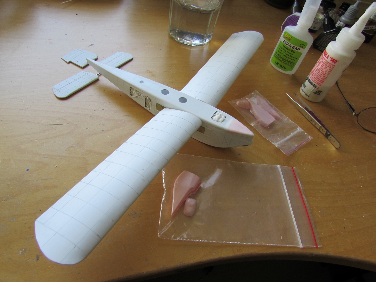
 The interior parts are produced and assembled. Cargo door, front bulkhead and cockpit floor, steps to access the cockpit (although many times the pilots accessed the open cockpit climbing from the tail on the back of the aircraft, as they did in the Zeppelin Staaken E.4/20):
 Dry-run of the seating. Steps into the cockpit installed, instrument panel and console being prepared in the background:
 A number of aluminum "Fairey-Reed" props are made, to select the best:


 Spanish Rohrbachs (and German for that matter) used a combination of different types of props. Laminated wood props and "flat" aluminum Reed props are seen in photos, as well as -in the central engine- what it looks like a Fairey adjustable pitch prop (looking a bit like your everyday Hamilton Standard, but not one of those).
 Just in case, two laminated wood props are carved as used by other Spanish "Rolandos":
 The variable pitch prop is made with a leftover stem and two carved blades:
 The indispensable facilities (especially considering the plane's registration):


Some of the interior structure is assembled:
 Dry-run of the seats:
 Dry-run of some of the components:
 Even the toilet roll -of real paper- is prepared, in case of emergency:
 Situation of the restroom behind the passengers cabin, and facing the entrance:
 A mirror and tap are made:
 The wheels are fabricated:


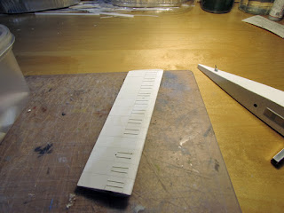
 The reinforcement strakes for the wing intrados are measured and cut, 40+ of them:
 and they are applied:
 All strakes/stiffeners (they are called "pichuflos" in Argentina) are now in place. The vacant space is for the engine gondola:
 The nose of the engine gondolas is removed from the wood master, and three separated sections are vacuum-formed:
 The front former and the engine support are cut from sheet styrene:
 Prop galore to cover all propeller possibilities:
 Another view of the components:
 The fin is given an internal re-enforcement that will support the stab spar:
 Stab is separated on its halves:
 Firewall is glued in place. Bathroom is attached. Seats are glued in place (first two rows were closer to the aisle, to give room to two frames that supported the wing spar:
 The frames are built:
 Dry-fit of frames on fuselage:
 Windows are cut on the mask, matching the inner and outer sides. You have to mask the inner side if you are airbrushing the cabin color:
 These are the times when I would like to have a mask cutting machine, like the Silhouette Portrait, and the patience to deal with software and computers, which of course I use, but mightily hate:
 It is interesting to compare sizes with another ongoing project, the Conqueror Gamma. It reveals the huge size of the latter clearly:
 The interior will now receive other colors. The bathroom will remain white, while the cargo hold will be metal to match photos, as well as the cockpit area:
 Instrument panel under way:

 Upholstery is added to cabin, tiles to bathroom:
 The radioman instruments and the toilet. All indispensable, but one more indispensable than the other:
 General view. Still more to be added, like rudder pedals, curtains, etc.:
 Bathroom furnishings, including toilet paper:
 The elements are glued in place:


 Even the toilet roll, with real tissue paper:

 Sink, tap, mirror, shelf, vase, are all there:
 And of course what the French-Canadian call "Alain's delice":
 Still to be added are the the pilots' seat belts, and the upholstery of the passenger seats has to be painted
 This is how a model looks before is put together:
 The interior is now complete:


 Some exterior parts are readied to be painted:

 The interior doors that separate different spaces are readied:

 The external batten reinforcements are glued to the fuselage sides:
 Doors are prepped and glued in position:
 Now the fuselage sides and interior can be glued together:
 Layout of the components (when I do this it feels like I am closer ;-) :
 Fuselage bottom in place:


 The spar needs to be glued at this stage in position, with the needed angle of attack. A notch is made in the fuselage:
 And the spar glued, watching not to glue the wings too, which are there just to check the position:
 Strip lengths are added in front and behind the spar. They will support a quarter circle rod that will give the upper fuselage its correct shape:
 The quarter circle rods are pre-contoured. They will have to be worked so there is a taper to the back:
 The engineering to accommodate the roof goes on:


 Dry-fit of the roof. Once in place a bit of filling and sanding should blend all in place:
 An idea of the size:
 The Small Stuff BMW engine. As said above, it is not exactly the model, but the lines are very similar. This is a jewel of a "kit", and very fairly priced. The casting is so perfect it is incredible:
 Components:
 Assembly begins, and goes on uneventfully:
 With just some care and patience, in minutes the basics are assembled. If you are so inclined, even the spark plugs are there with a tool to handle them, but this is beyond my eyesight:
 The looks are remarkable:
 I will be placing the engine in one of the gondolas, with a panel removed to partially show it:
 Some additional parts are glued to support the ones that will come next to complete the nose:
 The upper side of the nose has a more complex shape, and requires two volumes to depict it. The first one, horizontal, is a base, here made of basswood:
 The second, vertical, is made of a curved sheet:
 The wood parts is used to make a vacuformed copy:

 A last view of the interior, before the fuselage roof goes in:

 I decided to change the approach to the upper nose:
 And modified the parts accordingly:
 The effect is much better now:
 Dry-fit trial:
 The nose is almost ready now, only some small localized filling and sanding left:

 Nose smoothed:
 Propeller cone nuts in progress. Carve a cone on a black styrene sprue leftover, drill the center:
 Cut the tip, insert a toothpick, true the base against a nail file:
 Voilá! (or, as the German say: Güretrinkenshmelltzienpiptffesteinshnellganzescheinekleinebarfff):
 Circular windows are cut with a sharpened tube to fit in the openings of the fuselage roof:
 They are glued to the roof:
 And then masked both sides with Arctic Decals circular masks:
 Paint is applied to the inside, and those internal masks will be removed before gluing the part to the model:
 Ceiling lights are added:
 The top in place. Some putty and sanding will be needed to perfectly the surfaces:
 The top seams are puttied:
 Meanwhile, the fantastic decal sheet from Arctic Decals has arrived. As we previously discussed, the first reg this plane wore was M-CACA, hastily changed to M-CAAC a week later. I plan to do the same, photograph the plane in its first livery and then change it to the later one:
 The top is now smooth:
 Looking promising so far:
 And now, the engine nacelles:
 One nacelle will show the engine, panels left open:
 Work of adjustment continues:


 Dry-run:

 Engine glued to the frame (not possible to add it later as this is, and not wanting to make changes now):
 Styrene sheet tabs added to provide more gluing surface and alignment:
 The two nacelles sides glued. One as seen will show the engine:
 The wing roots have a little fairing or lip that to follow the fuselage curvature, so those are added:

 The nacelles noses are glued in place:


Frame is glued to one side:


I pulled two wind-driven generators from the spares bin. One was ok, the other was quite crude:
 The crude one was completely re-worked. Photos show variations on these generators from plane to plane, and among them in the same plane:
 The nacelles' seams are puttied:
 The Landing gear elements are measured and prepared. Their connecting points on the fuselage and wing drilled:
 Part of the tailskid in place:
 Holes are drilled on the wing for landing gear leg, radiator, and flying wire:
 Radiators are given their conduits, legs reinforced and drilled to accept metal locating pins:
 Gray primer is applied on all components:
 Tail surfaces:
 White primer is applied:
 All the black smaller components are painted:
 The making of details never seems to cease:
 Center engine exhaust piping and two external cockpit instruments:
 The grey-silver color is applied, a custom mix. Contrary to what you may see around, the planes were not white or cream or yellow, they kept the Lufthansa scheme with the addition of the Spanish colors under the wings, towards the tip :
 The three exhausts are airbrushed a dull metallic color:
 Then washes are applied:
 A bit or final dry-brushing:
 Same for the engine on the nacelle:
 White is airbrushed as an undercoat for the Spanish yellow and red flag:
 Yellow is now airbrushed:
 The yellow is masked and the red applied:
 Masks removed, flags ready.
The metallic reflectiveness of the "silbergrau" color makes the angled tips appear almost white:
 Masking everything and airbrushing the black color trim:
 Masks removed, touch-ups will follow where needed:
 Size comparison with the ongoing Fokker F.VIIb 3m project:

 And remember, children: always paint the %&%$#* ancillary parts at the same you paint the main components, so you don't have to go through the whole airbrush setting and cleaning twice just for two minuscule puffs of paint:
 Engine pods in, horizontal stabilizer and strus in, masks off:
 Arctic Decals sheet and masks are brought to the building board:
 Landing gear, window frames, props, radiators, wing landing lights in place, decaling begins.
On the right the windshield and other accessories are being prepared:
 The external instruments are prepared:
 A couple of photos where you can see the top of the Iberia planes do not show registrations there (but they did have regs. underneath the wing), but I am adding them since most likely they were applied later:
 Wind-driven generators and other details added:

See above for the link to the completed model.


The metallic reflectiveness of the "silbergrau" color makes the angled tips appear almost white:


On the right the windshield and other accessories are being prepared:


See above for the link to the completed model.
pls contact with
ReplyDeleteenricpallares@yahoo.com
i am interested in this 1/72
Me contactaré a la dirección provista
DeleteMuchas gracias or su interés.
Damn you! Another from my list of "to build one day".. lovely progress!
ReplyDeleteDear Tracy
DeleteThe slowest of them all this one is. But I am also looking forward to see it done.
I know it's a favorite of ours. But a kit will be out after I finish it.
I am tired just from watching you work- wow!
ReplyDeleteNot to tire, to inspire ;-)
Delete