
A 1937-born Barkley-Grow T8P-1, of course!
(this is the construction article, for the completed model please go here:
https://wingsofintent.blogspot.com/2018/04/barkley-grow-t8p-1-modified-execuform.html
(this is the construction article, for the completed model please go here:
https://wingsofintent.blogspot.com/2018/04/barkley-grow-t8p-1-modified-execuform.html
Continuing with the vacuum-formed building trend, here is a
product from Execuform, that gives you the basic shapes as a sort of base onto
which you have to add the detail you want. Only the main shapes come in the kit
with some leaflets containing a plan, images and information. The decals and
accessories (engine, wheels, cockpit and cabin detail) are to be provided by the
modeler. I have built products from this brand before and they should be
considered a white canvas onto which you can express your modeling artistry, on
subjects most of the time nowhere to be found as injected or resin kits. If do
some scratch-building, Execuform saves you a lot of time by producing the
masters and pulling the styrene shells, but they are not meant as complete
kits.
The Barkley-Grow was not a particularly successful design,
although it managed to operate with a number of airlines and private owners.
Three airframes seem to be still today being exhibited at museums.
The Barkley-Grow was operated on wheels, skis and floats,
making it especially useful as a bush plane in Canada,
where it saw a bit of recognition, negated to it in the US.
The seaplane version had an additional, smaller, central
vertical stabilizer. The land version had a fixed landing gear with
characteristic pants.
Of pleasant lines and uncomplicated design, especially on
wheels, it makes a good candidate to try your skills at this somewhat neglected
media. It teaches you in the process quite a bit.
Notable operators were Canadian Pacific, the US Antarctic
Service, Yukon Southern Air Transport, Pacific Western, Northland, Prairie
Airways, Associated Airlines, a private individual: Alexander Papana (YR-AHA,
Trăiască Regele "Long Live the King", same exact registration by the
way wore by Papana's Bellanca 28-92 trimotor), and the Peruvian government
(OB-GGK, Cruz de Chalpón).
This is what you get in the Execuform package. The basic shapes and reference material:


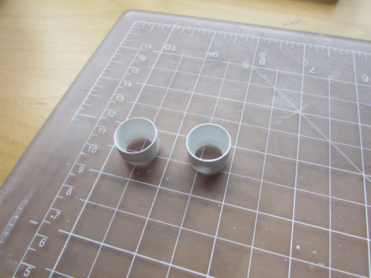
Separating the future cowls:


Belvedere (CF-BQM) had a blue fuselage and white flying surfaces and logo, with the floats in NMF.
My other options were also a seaplane flown by Pacific Western, with and attractive scheme, and a more traditional Canadian Pacific machine on wheels, just because long time ago my grandfather flew Canadian Pacific from Argentina to the US.
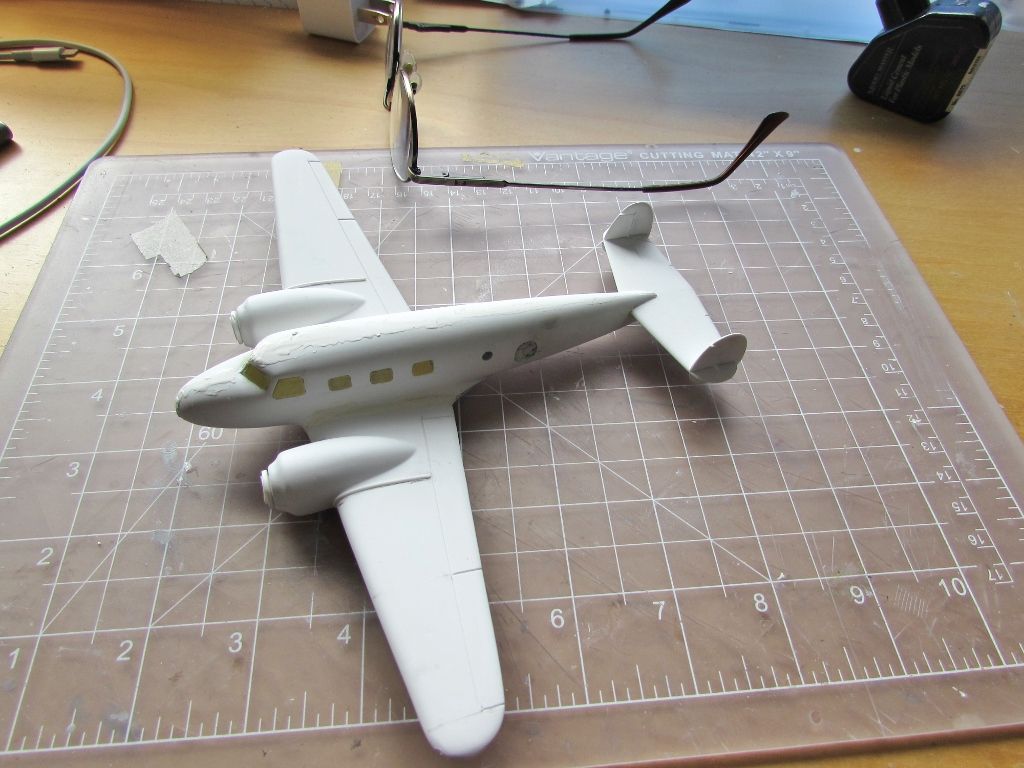
Here the cowls are dry-fitted to the nacelles. So far, if you did things right, the fit is good and the outlines are correct:


I made the intakes already for the land version, and here the other ones are being made from a sprue leftover, first heating and bending (be careful):


Here are the rudders for the floats, and metal pins being glued to the main float strut legs:


The instrument panel is cut:
 The landing gear legs (not the version I intend to build) had sleeves, so these are fashioned from a thin styrene strip:

 Once the glue sets the remainder will be cut off:
 The patch on the mold ding worked out well:
 Cargo area being detailed with bulkheads and stringers:
 Cockpit/cabin pan being detailed:
 Using the fuselage halves themselves, the contour of the doors is traced from inside onto a piece of styrene sheet:
 The doors are cut and bent:
 And then "hinges and handles" are added from stretched sprue. These will
be lightly sanded to make them rounder at the end that fits the part,
but the stalks will be only cut to size after painting, to facilitate
handling:
And then "hinges and handles" are added from stretched sprue. These will
be lightly sanded to make them rounder at the end that fits the part,
but the stalks will be only cut to size after painting, to facilitate
handling:
 A couple more elements added to the cockpit:
 The hatch for the cargo hold is carved:
 Tabs are secured to help alignment, increase gluing surface and add rigidity:
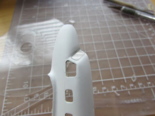
 Now dealing with engraving the control surfaces. The tail presents a
little dilemma. The fin/rudder separation line on the vertical
stabilizer is not continues, but, besides a balance mass, has a receding
line under the stab.
Now dealing with engraving the control surfaces. The tail presents a
little dilemma. The fin/rudder separation line on the vertical
stabilizer is not continues, but, besides a balance mass, has a receding
line under the stab.
Furthermore, the rudders are "inserted" on the stab, whilst the fins divide in upper and lower halves. Summarizing: you can either cut the stab tips to add the vertical stabilizers, of you have to cut the latter.
I opted for the second option, also separating fin and rudder. This will give us at the beginning fours parts, but the rudder upper and lower sections will be glued, as per original, at their trailing edge. You will have to study photos of the original plane to decipher what I am talking about:


 The upper and lower rudder will later be "reunited" at their trailing
edges. As you can see, the rudder "flies" over a fixed section of the
stab:
The upper and lower rudder will later be "reunited" at their trailing
edges. As you can see, the rudder "flies" over a fixed section of the
stab:
 The first move is to separate upper and lower halves, then carve the
curve to follow -always checking as you go- the airfoil of the stab:
The first move is to separate upper and lower halves, then carve the
curve to follow -always checking as you go- the airfoil of the stab:
 The reinforcements at the exterior side of the nacelles -a la DC3- cover
in the original wing external panels joint. I used the smallest section
of semi-circular styrene rod:
The reinforcements at the exterior side of the nacelles -a la DC3- cover
in the original wing external panels joint. I used the smallest section
of semi-circular styrene rod:
 The interior is given the first color:
 Reinforcement battens are added to the floats as per photos, the trolley wheels holes drilled:
 A second and third color are airbrushed:
 Details will be picked up by hand now:
 The Aeroclub engines as said before are a perfect fit for the cowl, but
the sub-assembly needs a separator to generate the right distance to the
nacelle, so discs of styrene are prepared, to connect the firewall to
the back of the engines (leaving a necessary gap between cowl and
nacelle):
The Aeroclub engines as said before are a perfect fit for the cowl, but
the sub-assembly needs a separator to generate the right distance to the
nacelle, so discs of styrene are prepared, to connect the firewall to
the back of the engines (leaving a necessary gap between cowl and
nacelle):
 Tail is assembled. The central fin is a bit roundish in the kit, but
photos show that its LE and TE were straight, so the part is accordingly
easily reshaped, and given the "tail-up" cut to clear the "elevator up"
position:
Tail is assembled. The central fin is a bit roundish in the kit, but
photos show that its LE and TE were straight, so the part is accordingly
easily reshaped, and given the "tail-up" cut to clear the "elevator up"
position:
 Slightly oversized pieces of acrylic are cut, then shaped to fit the particular window, one by one:


 Once fitted, they are removed, aligned to follow their respective positions, and one by one bathed in floor polish, excess removed on a piece of card, and let to rest leaning on a surface.
Once dry, they will be positioned on the model, and very carefully given a very thin touch in the borders with low density cyano, letting it run the seam.
Once set, the windows will be masked on the outside, and the fuselage sides glued together. It just tired me of writing it!
The curtains are added:
 Ready to proceed:
 Fuselage halves glued together; the exhausts are given pins to secure them on the fuselage bottom as per photos:
 The yawning gaps and not so good fit called for drastic modeling action,
so 10 min. epoxy had to be used to glue the wing to the fuselage,
giving plenty of time to make adjustments and material to fill the
enormous gaps:
The yawning gaps and not so good fit called for drastic modeling action,
so 10 min. epoxy had to be used to glue the wing to the fuselage,
giving plenty of time to make adjustments and material to fill the
enormous gaps:

 Here Milliput, as said above, was added on top of the wing/fuselage joint.
Normal putty is on the seams elsewhere. All that of course has to be sanded to proper contour.
A cut is made to lodge the stab:
 And the stab glued in place, taking care of allowing a theoretical elevator down movement.
Next to central fin is going to be glued, but after I tidy the seams in the area.
At this point, will all the putty, is when models don't look really appealing.
 A little bit strange, but the B-G (or at least Belvedere) had the
bottom of the floats painted red (red underfloats, as they are known in
the Ornithopter modeling community).
A little bit strange, but the B-G (or at least Belvedere) had the
bottom of the floats painted red (red underfloats, as they are known in
the Ornithopter modeling community).
At this point engines are given a base coat of black paint, and prop tips are painted yellow as per photos:
 Ready for the first coat of primer:
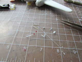
 Antennas, scoops, beacon, etc., being prepared:
 Ladder that goes from float to door also built at this point:
 The primer revealed as usual a couple of spots that need attention:
 Several cleats are made to chose the better for the floats:
 The red under the floats is masked to apply the black color for the Alclad:
 The white color is applied to the fuselage and engine cowls.
This will be partially masked to apply the blue color eventually.
Aluminium color is applied to floats, float rudders, and ladder:
 The bottom of the floats is unmasked to reveal the red color:
 I had forgotten the faired scissors linkages under the wing, so I made the five pairs that decrease in size towards the tip:
 The decals from Arctic Decals arrived!:
 The model is masked to be able to paint the blue color:
 The details on the spine are added:
 The blue color is applied:
 The round lids made of punched alu sheet are glued in place on the floats.
Still to add are the mooring cleats and succinct rudder rigging, plus painting the nose black:
 Et voilà:
 The floats are added. No small task to glue and align them:
 Exhausts made of alu tube:
 Getting closer to completion:
 Little by little all the bits are added. Ladder, engines and cowls, floats' rudders:
 The float tips are painted black
 The fairings of the scissor links under the wings and decals:
 Mooring cleats, boomerang antenna, spine antenna, props, rigging for the floats' rudders:
 Preparing parts for the beaching gear:

To be continued.....


Furthermore, the rudders are "inserted" on the stab, whilst the fins divide in upper and lower halves. Summarizing: you can either cut the stab tips to add the vertical stabilizers, of you have to cut the latter.
I opted for the second option, also separating fin and rudder. This will give us at the beginning fours parts, but the rudder upper and lower sections will be glued, as per original, at their trailing edge. You will have to study photos of the original plane to decipher what I am talking about:


Once dry, they will be positioned on the model, and very carefully given a very thin touch in the borders with low density cyano, letting it run the seam.
Once set, the windows will be masked on the outside, and the fuselage sides glued together. It just tired me of writing it!
The curtains are added:


Normal putty is on the seams elsewhere. All that of course has to be sanded to proper contour.
A cut is made to lodge the stab:

Next to central fin is going to be glued, but after I tidy the seams in the area.
At this point, will all the putty, is when models don't look really appealing.
At this point engines are given a base coat of black paint, and prop tips are painted yellow as per photos:


This will be partially masked to apply the blue color eventually.
Aluminium color is applied to floats, float rudders, and ladder:


Still to add are the mooring cleats and succinct rudder rigging, plus painting the nose black:


To be continued.....
This comment has been removed by the author.
ReplyDeleteHi Claude
DeleteIf you read above, you will see that I stated that was inclined for Belvedere, a seaplane in blue/white/silver (CF-BQM).
Papana's plane is all silver, nice, but a bit unappealing, and not on floats.