


(The completed model is here:
https://wingsofintent.blogspot.com/2021/09/caproni-ca-101-ala-littoria-converted.html
Here a link to I-ABCQ:
(NOTE: some source states that some versions had a slightly different span and length, I have been trying to ascertain this, and, for example: "Aeroplani Caproni dal 1908 al 1935 - Caproni G." does not state a different span, nor does "Italian Civil and Military Aircraft". There was a difference in length, though, as the nose changed to accommodate other power plants.
Addenda: Aeroplani Caproni, written by Abate - Alegi - Apostolo, states span differences between the 101-less span, 101 bis and C -same span- and E -more span (thanks Fabrizio!) The kit's span is in the general ballpark of the bis and C types.
When the Caproni Ca.101 appeared in the market released by Fly, I acquired one, even if it wasn't the civil version I was hoping for, as I knew the chances of having it marketed by the manufacturer would be close to null.
Then I spotted a later LF release of what looks like exactly the same molds
https://www.scalemates.com/kits/fly-72050-caproni-101--1326407
that features the civil registration I-ALBA among the decals' options, and suggests in the instructions the necessary mods. Problem is, the decals are not totally accurate, as I-ALBA shows in a the only photo I found the then common long bars below the regs on fuselage and wing. Besides, the modeler will have to plug the dorsal opening and provide for the passenger cabin, discarding all the bonga-bonga equipment. I see no mention of that in the instructions of that boxing, other than to install windows and drill a porthole in the door.
Browsing through my files for a suitable conversion of the kit, I came across several candidates, one of them, I-ABCQ, presents an interesting option. Photos show the plane in three different schemes:
1) As a sort of joyride (photos above) that toured Italy giving the locals
flight experience, in what looks like perhaps ivory color with black regs, with
seemingly black nose and engine gondolas, provided with passenger seats and
windows. Here is a movie of it. The door is slightly different and it has full passenger capacity (other versions that operated long routes had less seats):
https://www.youtube.com/watch?v=jf2AfW4JOaI
2) In some undetermined color and white regs on fuselage, and color regs on white background under the wings. Windows fully or partially deleted, equipped with four loudspeakers inside the fuselage, and two compartments for technician and speaker.
3) Another incarnation of the plane in colorful livery, also
with sound system equipment for aerial advertisement, with perhaps only two
windows visible, and owner's company (La voce del cielo) motto on the nose
("Vox coeli vox populi"). The only photo I found (in Airhistory.net) of
this version shows it on the tarmac in Holland,
where reputedly announced Verkade biscuits. I found several contemporary
newspaper articles stating its flights, broadcasting music from an altitude of
about 1.000 meters.The power for the broadcast system was obtained via four wind-driven generators of one-blade prop, located under the wings (two and two). The blades were adjusted automatically as to provide a constant current at all flight speeds.
An article in Italian on vintage radio and communication equipment provided some additional info, and, what's better, photos (but not good ones) of the exterior and interior (for the second scheme).
For this candidate the engines that come with the kit would do, but other civil airframes I am considering and researching would require after-market engines (Bristol Jupiter and Lynxes). These planes with alternate powerplants seem to have, studying photos, a shorter nose of slightly different shape to compensate for the Jupiter engine. Links to GAVS:
I-ABCB https://gavs.it/rci/record/589
I-ABCC https://gavs.it/rci/record/590
I-ABCJ https://gavs.it/rci/record/598
I-ABCK https://gavs.it/rci/record/599
I-AAZA can be seen here:
https://www.youtube.com/watch?v=HBq3PBhrxXg
All these planes have some variations in details, among them:
a) Different power plants, different exhaust arrangement, different propellers -in some cases rotating in the opposite direction than those in the kit
b) Details on the landing gear legs
c) Different doors
d) Different window arrangement
e) Different interiors
f) Variations on the nose shape
so a choice will have to be made soon, as modifications need to start early in the build (window arrangement, for example).
The kit: Interesting level of interior and exterior details,
perhaps just a bit heavy handed on some items, with a feeling that leans
towards hefty, and somewhat thick molds. Plenty of ejector towers that will
have to be dealt with, some flash. The resin parts add to the package, but I
ordered the Brengun P.E. detail set to improve or replace some of the kit
parts, and add others. Some fragile details on the resin parts came already
broken, as it's often the case when resin parts are bagged together -heavy and
delicate ones- and suffer the cocktail shaking of transportation. The engine
cylinders will require your participation adding the pushrods for each cylinder for the three engines. How fun. The
engineering seems sound, but some solutions are perhaps dubious: the front
transparency is split in two parts, right in the middle. I haven't seen this
since Paleolithic kits. Of course, in order to civilize this model, some parts
will be discarded (pim-pum-paf parts) and others will need to be fabricated,
once I decide the path: loudspeaker plane or passenger carrier.
Contents:


Some parts that come in halves are glued together. As mentioned, there are no locating devices for most parts. The feel, hefty weight, and "solidness" of the parts and sub-assemblies remind me a bit of Valom kits:

Before advancing much further, the specific plane to be modeled has to be chosen, as subtypes varied, and the above-mentioned broadcasting plane had no passenger interior:


Of course the dorsal position on the mold has to be occluded (dry fit):


The pencil line shows the shape of the door for the loudspeaker plane (and some of the other civil versions):

Just in case, the kit's engines are assembled. They are sort of generic in appearance, and the corresponding props rotate anticlockwise seen standing facing the nose of the plane, which is not accurate for some of 7cylinder power plants the plane used (Lynxes, for example):

As I order the Brengun P.E. set, I have to wait to start the cockpit, a sub-assembly common to most versions, as the set included an inst. pan. and pedals to replace/complement the kit parts.
I changed course midway and instead of going fore the loudspeaker version, will do a full passenger version at the service of Ala Littoria, I-ABCJ, and already started to modify the fuselage for that.
The plane had a two color scheme (I am guessing light blue and ivory), it had almost straight, horizontal mudguards, a Jupiter engine in the nose and two Lynxes as explained above, 8 seats (six in cabin and two "second class" in the back, and bathroom:
From "Aeroplani Caproni dal 1908 al 1935 - Caproni G." (the page describes a similar interior, not the one in the plane I am modeling, which has some changes):

The modifications are not made easy by the thick and hard plastic, which, as I said above, reminds me of the Valom plastic:


The three bulkhead frames included in the kit have to be consigned to the trash can, as this interior needs full bulkheads with doors, and the "structure" inside the fuselage side has to be covered with sheet styrene:


As far as I can tell, and according to all the photos I have, Fly missed the auxiliary strut that connects the aft wing strut to the fuselage. This is easily correctable, and surely from the spares bin a coupe of suitable parts can be adapted -or just scratched, still, a little bit of an obvious omission on part of the manufacturer:

The notch on the aft wing struts should point out, not in as in the instructions, that will have you locate the nacelle tip in it. It was actually where the missing secondary struts attached:


Engine assembly completed...but not quite so. The pushrods at the front were omitted by the manufacturer, and have to be added from wire, stretched sprue and the like.
The broken mudguards are repaired with metal lengths, in any case the kit's feeble supports, if not broken in transit as they did, would have broken soon after anyway, as resin has very low mechanical strength in thin items:


Work on the interior continues:


Dry run of the seats. And yes, the restroom had a window!:

As mentioned the kit's props (background) rotate in the "wrong" direction for the engines I am employing, thus new ones are being made of laminated thin plywood:

The props are ready. The one for the Jupiter has a slightly bigger length:

The engine fairing is added to the engine nacelles, as it fits quite well the new aftermarket item. The photo-etched set has arrived. Only a very few items can go in my version, so most of it will go to sleep the long sleep of the spares bin:

The structure is covered in paneling, as it corresponds to an airliner. Notice the addition of sheet spanning the gaps where the top position and belly window were. They will help as support later when adding the tailored styrene sheet plugs once the fuselage halves are joined:

A coat of primer to a group of components:

As mentioned before, the canopy comes split in to halves, as the geometry is a bit complex and the sides lean inwards. But the two-part is a less than ideal solution for a number of reasons, all too obvious. This canopy needed a multi-part mold, something the industry understandably avoids of course because it's expensive. So the problem is passed to you, the modeler. I used an enhanced strength acrylic glue, and may use a P.E. part that comes for it spanning the two halves that may help stabilizing it, we'll see:

One thing neither the kit nor the aftermarked P.E. set provide is the rudder control horn, I found one in my spares:


As an example: the canopy in the kit does not match any of the photos I have (but who knows, there may be other versions). You can clearly see here four oval windows, and what seems like two rectangular transparencies on top. The geometry of the side panels is different from those in the kit. Visible here are also the control cable bars on the fuselage side:

The image above is a detail from a photo on Wikimedia:
And whilst the more recent LF release does include the clear parts (and paint) masks, the Fly version doesn't, nor I could find an a.m. set for it.
The oil fillers are made and inserted in the nacelles:


Clarity and appearance improve as usual with a bath in acrylic floor polish:

A base coat of paint is airbrushed on several parts:

Progress with the engines and interior:

And now the acme of the scratchbuilder: the toilet roll!. It begins spreading glue on a length of narrowly trimmed real tissue paper:


Dry-fit check to see how things go:


The landing gear legs and mudguards will be painted metal color together with the engine nacelles:


Fred Hultberg of Fotocut used to make and sell fantastic ones, now sorely missed (both, Fred and his products),
together with many of his wonderful photo-etched items, which were varied, affordable and absolutely useful. Instead, I have
acquired similar oil coolers from a German outfit that I will adapt to the model:

The windows are cut from acrylic sheet. Dry-fit test to make fine adjustments:


Wheels painted, nacelles with base coat for the metal color, interior of luggage hold:

Looking closely at the photos of the chosen plane, I realized that the other pair provided of landing gear legs applied, so these are prepared. Some times with little effort we can improve the kit's parts:


A bit of painting:

The nose of the Jupiter engine version was different. I am using the kit's resin part combined with a length of aluminium tube that will be the base of a recreated part, together with the alteration of the nose shape:


A few structural wires are added from inside before uniting the fuselage halves:

The new exhaust rings are completed:


The ventral plug in place:


Tail feathers go in:


The tailwheel unit is glued to the model. The canopy is masked (no masks in the kit and no aftermarket offers for it, so, by hand) and added. The canopy (that very unfortunately comes split in two halves) does not accurately represent any of the ones in the photos I have. It's close, but not really accurate.
Which leads to the next rhetorical question: Why it seems that manufactures base their kits on plans, but apparently do not use photographic material to check them? One of the many mysteries of kit manufacturing.
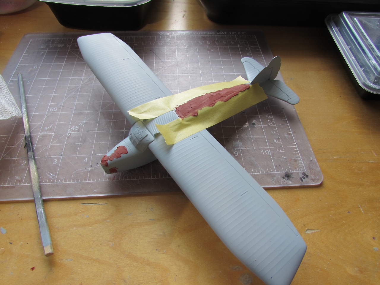
Well, all seems quite ready for the last stages. It looks like the more laborious task ahead is the re-contouring of the nose (Milliput in bulk is already applied underneath it, not visible in this photo), and then the first coat of primer to detect imperfections; and if all goes as it should, then masking, painting, decaling and general assembly:

Given the poor optical quality of the transparency, almost nothing is seen of that detailed cockpit, so I guess that I was right in not using the P.E. enhancements, as nil would have shown really. To compensate for that, at least the opened door, cargo hatch and extensive cabin windows will add some interest to the model, plus the much better detailed aftermarket engines and colorful livery.
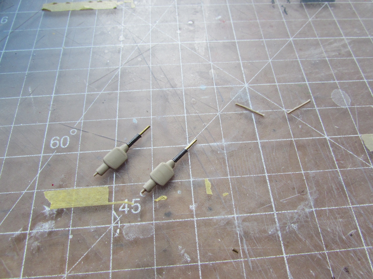
The stems and fairings for the nav lights (absent in the kit) are fabricated. Once painted they will get resin colored lenses:

The nose being re-contoured:

Some aileron linkages arrived from Germany:


First coat of primer revealed a few spots that will need fixing:


A cycle few modelers ever escape: filling, sanding, priming; vividly portrayed in the films "The Groundhog Day" and "Live, Die, Repeat":


Not so fast, cowboy. It looks like we will have at least one more round...:
The nav lights are ready. One stem is a spare in case something happens:

And now ready for the coat of the first color, ivory:

Meanwhile the ancillaries, that will be blue, are given a coat of white primer:

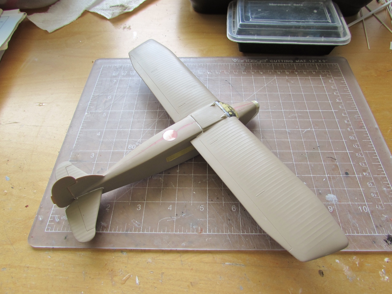
The ivory color is airbrushed:

Blue is airbrushed:


Most masks off:

Ahead is now the task of adding the frames to the side windows:


The external control bars on the right fuselage side, fore and aft (absent in the kit) are installed using aftermarket P.E. items. Wing and tail struts are added. I can't run the control cables as they go over the decals (which I don't have yet). The easier sequence would have been adding the decals, run the cables, and then add the struts, but it can be managed this way too with some contortions. The length of strut on the background is to add that diagonal piece to the aft wing strut (the same as the fore struts), that the kit missed completely:

The aftermarket radiators are assembled:


The fit of the struts and engine gondolas is quite poor. If not adjusted and refined, nothing will seat as it should. If this is something that is anooying to do when the parts are not painted, I really hate to adjust parts when they are already painted, as you are bound to mar the finish and then have to do touch-ups. The initial impressions of coarseness regarding this kit are further reinforced:

The reinforcement struts that the kit missed, and were previously fabricated, are now added:

The landing gear braces, vertical legs and wheels are added, as well as the wind-driven generator and the oil coolers:

The commissioned set arrived from Arctic Decals, and application begins:

The kit's heavy-handed chunks of plastic mentioned at the beginning produce of course a hefty final weight, so after a few weeks of standing on its wheels, the axles started to give way and the wheels started to splay. I recommend to modelers building this kit to replace the wheel axles with metal items to avoid this issue. I resorted to add cyano glue in the area and apply accelerator in a effort to confer rigidity. Time will tell:

The external control cables and their runners are added:

Center engine, props, nav. lights, aileron linkages and remaining decals were added. Photo session over the weeks if weather allows it:

To be continued....
No comments:
Post a Comment