Or at least Dinosoars.
And the Kangaroo (that is but just a smaller, furry, boingy tyrannosaur) is the proof.
I agree...looking at the shape of the plane you may -justly-
ask if its name was applied because it only managed to hop around. Well, no. It
really flew. True.
Uninterested as I am on bellicist endeavors, I was elated on
discovering the civil version of this plane used mainly to provide joy-rides
and the occasional passenger transport service. A few of these planes
-leftovers from the butchery of the second decade of the XX century- were
converted as said, and in this case an "enclosed cabin" was provided
for the comfort of the naive passengers, whilst other versions had them exposed
to the elements.
I am in debt with Renald Gravel -and Alain Bourret- who
facilitated my acquisition of this sort of vintage kit -that is not abundant-
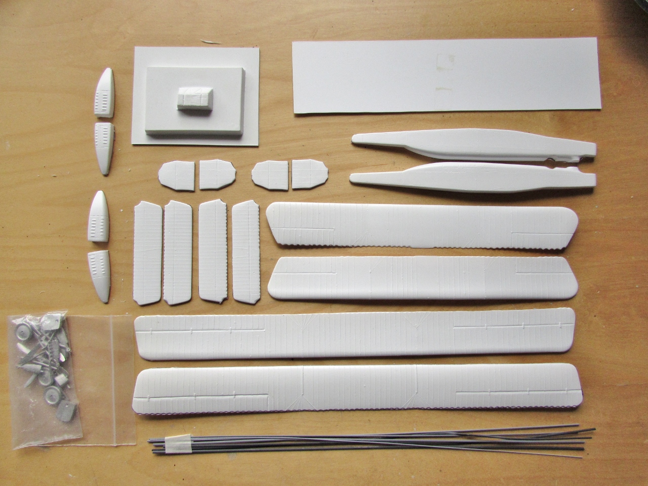
under very fair conditions. As you can see in the photos this Contrail kit is
molded with an acceptable level of detail, if the surface is not perfect. The
bonus here are the white metal parts, of standard quality for this type of kit,
a small assortment of Contrail extruded styrene stock -shaped as airfoils and
as rods-, decals, and an extensive plan. The best part of this kit is the
plastic, which combines all the desirable features: resilience, reasonably
uniform thickness -meaning no frail translucent plastic where the sheet is
pulled far away from the backing surroundings-, right thickness overall making
it very easy to work with and both rigid and flexible enough. There is even an
additional part that is used as a cradle to align the structural members of the
engine supports. There is a little pattern on the plan to make the floor, but no interior is provided. A seat is shown on the plan, but I did not find any, either molded or provided as a white metal part. In any case, a whole interior will be provided, cockpit and passengers' seats and partially open cabin with an access ladder as per photo I found. Some clear material will be needed for windows.
I purchased the superb set of Arctic Decals to further
enhance the model, consigning the kit's decals to the spares.
I am planning on substituting some of the extruded Contrail
airfoiled material for brass Strutz -for which once more I have to thank Andrew
Nickeas- because the Contrail stock is a bit flimsy.
Parts are easily scored and cut away. The task of marking the parts, scoring them with a new blade, taking them off, and sand them to proper thinness took less than two hours:
All the components ready.
I am trying a length of PART's photoetched "1/72" stitching, which compared to photos is way overscale:
Tom Modelworks' stitching seems spot-on, will have to order a couple interior sets to cover the length, though:
Closer examination of the fuselage revealed a few inaccuracies. Bellow, the shape of the fuselage:
A few notes on the fuselage, which leaves quite a bit to be desired. The kit plan and box correctly show a "broken" mid-fuselage "stitching line", whilst the actual part has engraved a straight line. Furthermore, the part detail wrongly shows stitching above and bellow that side fuselage, whilst it was located only above (and along some vertical seams) :
The fuselage surface detail may have to be erased and re-traced, the "cabin" cut out and a newer cabin made.
The decals I purchased arrived today from Arctic Decals in Finland; neat, well-packed, comprehensive, well-researched, as usual:
Today I got the Bristol F2B kit from Roden. Why? to get the engine from it for the Kangaroo:
I respect Roden and I like their kits, but there is one thing that invariable spoils the quality and ease of building of their models: They surround the small parts with very thick sprue gates, pointing to every conceivable direction, making their removal and clean-up a nightmare. Invariably, per rule, I'll end up breaking a few parts due to the -impossible to avoid- stress they are subjected to during the process of cutting them out. Come on, Roden, look for example at Jordan Highway Miniatures, 1/87 injected styrene railroad kits made DECADES AGO. They are impeccable, sharp, detailed, much smaller than any Roden 1/72 kit and yet you can get the parts out of the sprue with much more ease, there is no flash (present in Roden kits often) and the detail is outstanding. Time to learn something, Roden:

The parts for the engine are separated. The broken one were glued back together. Thick injection gates in the sprue makes clean-up of the smaller parts a very annoying and frustrating task. Many times you can't see clearly where the part ends and the gate begins. The so-so drawings on the instructions don't help much. Sad:
But at least we have the correct engine, not available anywhere as an aftermarket part (that I am aware of). The F2B kit will reincarnate eventually as a civil conversion with the engine hood on and a covered passenger cabin.
The assembly did not take long, but believe me, look at actual photos of the engine on the Net, the instructions are really not much help regarding precise positioning, at all. I did not follow the instruction steps, founding them not practical. I glued the cylinder banks to the block and then added the details:
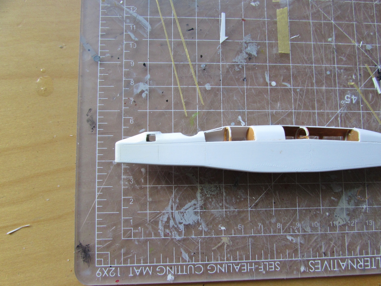
The portion of the fuselage that is inaccurate is removed, after tracing a new angled top longeron line:
One engine gondola is opened up to consider how much of the panels should be removed to be able show the engine to good effect:
Some bulkheads are added:
Some flooring is prepared:
The seats are made and glued on the floor:
The cockpit in progress:
Nice sunset:
Labor on the interior continues:
A more careful scrutiny of photos revealed that there were two fore passenger stations; the layout is thus modified:
The front and side windows on the nose position are created. The instrument panel is almost ready:
General colors are airbrushed, detail painting will follow:
Almost ready to close the fuselage:
Inst. panel in place. As usual with vacuum-formed kits, some styrene sheet tabs are added to one side to augment gluing surface and help with rigidity:
And work progresses..:
General view of the components:
The section of the fuselage top that will support the central wing struts is formed:
The cradles for the engines are built with thin rod stock. I ended up not using jig provided in the kit for this purpose, since it proved to be out of kilter:
The white metal fittings are given a cleanup:
The fuselage top receives its spine. To it the hatches that from both sides allowed the passengers to be loaded will be attached. The cradles for the engine gondolas are completed:
The addition of side "hatches" continues. All the right side will have them closed, and the left side open:
And the labor of producing and adjusting hatches one-by-one continues. All these upward-opening hatches can be seen in photos, and all have the windows as depicted but the first one, which slopes upwards from the cockpit aft. I can't see windows on that one on the sides as the other ones, so I am guessing for that one the windows shown as vertical. One single photo may hint, faintly and not with clarity or certainty though, at a circular or curved window, an option I discarded in favor of the arrangement shown. Again, all these guess is just for the first section immediately after the pilot (second "hole" for you unwashed, the first "hole" was also for a passenger). All other windows and hatches were verified in photos:
The hatches for the passenger access are made (left side). These will be posed "open":
The kit has an inaccurate upper nose tip profile, which should slope upwards to meet the first position (the first round opening on the fuselage):
The shape is changed with Milliput and patience:
Working now on the wings, I was checking the alignment of the holes for the struts, when I noticed the on the right panel the holes for the superstructure that supports some rigging on the top surface did not align with the struts underneath.
After careful examination, I discovered that was yet another Contrail mistake.
I filled the top holes and re-drilled them in the right spot.
The origin of this error is the previously-discovered Contrail mess-up of the left aileron top and bottom surfaces (the aileron bottom detail is correct, the top isn't as it is shifted one rib bay), explained above. This translated into having to erase the hinges (which of course do not symmetrically reflect the right side) and making new ones positioned one bay towards the tip:
The right panel holes are re-drilled and the incorrect ones -that were marked in the molds as a guide-filled-up:
Hinges in the left aileron incorrectly molded by Contrail. They do not reflect the right aileron or the same left aileron itself bottom detail:
Right aileron wrong holes filled-up, new ones made. The hinges on this one are correct:
The bottom of the left aileron showing the correct position of the hinges on the mold,
not followed by the manufacturer on the top:
Wrong hinges positions erased:
New ones made of bits of styrene, later -once dry- to be blended on:
Long ago I have made my own "stitching" decals. They may be used on this project:
A not-so-glamorous stage: puttying and sanding (the kangaroo fuselage to the right):
The tail assembly is half-built, introducing metal pins for the fins to better secure them. The lower part needs its center section removed to allow for the fuselage tail:
Once all (we hope) the kit's many inaccuracies and quirks are corrected and the major
assemblies completed, a priming session ensues, also covering the
variety of kit's metal parts:
The front of the nacelles is sawed-off, in order to later attach the metal radiators. If you don't do this the front will be too long:
The parts involved in this sub-assembly, including an added engine from another kit:
The upper stab and the upper wing underneaths are painted CDL:
A home-brew of PC10 is created and then airbrushed first in small parts to check the results:
The lower stab is separated in its left and right halves. Metal pins will be used to secure it:
The lower left and right wing panels are given brass spars. Indentations are carved in the fuselage to receive them, as it was in the original plane:
The spars will be half-hidden, again as per photos:
Location holes are drilled for the lower stab, upper wing fuselage struts, elevator horns, Pitot support under the fuselage. The scratched tailskid is glued in place:
Using the metal spars the wing and stab are glued to to the fuselage:
This is a large model in spite of its 1/72nd scale:
Whatever is white, CDL, or PC10, is painted so:
Undersurfaces of top wing and top stab are CDL:
The protective tissue paper is removed from cockpit and cabin:
You learn something every day...but sometimes I learn
the same thing every time. When you paint the main parts, you may also paint the small ones, if the color is the same:
The material provided with the kit to make the struts is too flimsy. I made mine with brass Strutz (once more, thanks Andrew Nickeas!) and some old Contrail stock for just a few that are of a bigger size (the ones to the external side of the engine, at the front). Those differently-sized struts are mostly missed in the builds I have seen, but are clearly shown in photos. Other sizes will be employed in the fuselage-to-wing struts, and the ones on the tail:
Further painting of the small parts ensues:
At this point I declare this build a work of love. Internal struts are PC10 (and one is significantly larger than the normal ones, a fact overlooked by most builds), whilst external ones are white. The props can be seen now with their splitting-preventing linen sheaths:
The windows are filled with acrylic -still drying- and the radiators are glued to the engine gondolas:
The positions where the gondolas' structures attach to the wing are slightly carved down to follow the original:
The gondolas are glued to the wing and propped until the cement sets. Around them, the struts will be erected, and auxiliary supports added as per original:
Struts in place:
Top wing in place:
Comparative sizes of two ongoing projects:
Once the landing gear, the tail, and some additional structural elements are in place, the long journey of rigging and adding the control cables will begin. Not a weekender, this one:
Some more structural elements in the engine area are added. The landing gear is now in place.
The white metal parts of this kit are weak, feeble, extremely heavy and have the rigidity of Plasticine, utterly annoying. The tanks you see in the foreground that go on the inner side of the engine structure will be replaced with scratched, lighter ones to facilitate positioning and gluing. No wonder the built models I see on the Net are sometimes not really good, this is a kit you have to fight your way through, and seriously commit to if you want a good result:
Scratchbuilt tanks:
Upper stabilizer and vertical stabs in place, as well as aileron connecting rods and LG diagonal reinforcements. At this time is like a game of a reverse Pick-Up Sticks, trying to put one in without disarranging the others:
And you work for a couple hours and there seems to be no difference. Some engine, wing and tail structure was added, plus the oil tanks:
Decaling begins using the Arctic Decals set. In this type of decal you have to cut each subject apart, trying to leave as little carrier as possible around the image. The decals behave well and give you time to position them, but a bit of setting solution may be needed on the black ink subjects:
Since some rigging goes over the lettering, it is wise to apply the decals at this time:
I had to discard the already prepared and painted kit's exhausts. They won't fit correctly once you build the pod and struts as the kit is supposed to be built. The space is too tight. Once more, the kit evidences lack of checking. Not only that, but the kit metal parts are too short. Photos show the exhaust pipes running barely passing the aft strut, while the kit's fall very short of that. Photos also hint at a diagonally cut end, whilst the kit pipes end just perpendicular to their length.
To deal with a project of such complexity is not very easy to start with, and although I am very grateful that a kit of this plane does exist, I wish it would be better.
I am preparing styrene replacements:
Details and more details....
The Pitot probe is made up of spare parts:
The elevator control horns are cut from metal:
Racks that run along the fuselage at about the trailing edge are added, as well as the axis for the elevator control horns:
Two horizontal sections on the vertical stab struts are added:
Eight pulleys (the very small black disks) are added to the stabilizer:
When all is said and done at the far end of the model, 32 lengths of wire (some are underneath) have been measured, cut and glued to represent the control cables and the rigging:
Rigging moves on to the wing fuselage center section:
The more advanced the construction, the more difficult to add the remaining parts:


 The upper and lower halves of wings and stabs' details (rib lines, partitions, holes for the struts and such) do not really coincide well, some compromise has to be obtained. The idea of having the wing panels all in a continuous part I think is good, so you don't have to deal with individual panels, dihedral, thicknesses, etc. but less care than needed was used by the manufacturer in aligning the upper and lower halves. Did they not build their own kit? The ribs, well, it's a bit difficult to make them all coincide, but an aileron short by one rib, really? Not even an errata piece of paper to warn modelers? ts ts, Contrail...:
 Try to thin the trailing edges as much as you can, sanding and shaving carefully from inside:
 Original sheet thickness shown on the fuselage edge, thinned stab:
 The wing will admit less thinning, because of the way the scallops are molded:
 The flying surfaces halves are all glued together. The locations of the struts -already drilled here- are marked on the parts from factory. As said, the parts will not align exactly, so use your good judgement (for example, on the stabs and fins, use the hinge line to align the upper and lower -or right/left- halves):
 Fixing the incorrectly molded aileron tip and the scratch on the molding of the stab:
 The engine gondola halves are glued together. One will later be opened up to show the RR engine.


It's a brave effort, Claude! Keep on working! (YOU! building a bomber? oh well!)
ReplyDeleteA bomber you say, Diego?
DeleteNot so, unless the passengers went to the restroom in flight...
Welcome to the wonderful, wacky world of Contrail.....a place where it's usually easier to start from scratch. Proprietor Gordon Sutcliffe
ReplyDeletewas kind of Gordon Stevens' equally prolific, but much less-fastidious contemporary. The pair of them dominated vac-land for 20 years.
I assume you are using the excellent
Windsock Datafile on the Kangaroo...
Roger, you made me laugh :-)
DeleteI have gathered a not so thin file on this one, but I don't have the Windsock, although some of its pages have circulated here and there and I took note.
But no matter what references I may gather, the results will always be far bellow your outstanding creations.
Be well
Woof, I have this one to build as well. Keep going, we are all watching!
ReplyDeleteDear Tracy
DeleteAn interesting challenge this one is.
Will be continuing soon, now that the very demanding Westlands are done.